diy solar

diy solar

Victron Charge Controller Battery Protect

Duddy

New Member
Joined
Apr 16, 2020
Messages
4
Hello,

After recently coming across Wills videos i decided to upgrade my small system with a Victron 100/20 SCC but noticed that Will mentioned not to use the battery disconnect with the inverter. I tried to search but could not find anything so if its a repeat post i would appreciate it if you could point me in the right direction. My inverter does not have any remote connection so what options do i have to make have some sort of battery disconnect protection in place?

I just bought a new inverter so dont really want to buy another one but if thats the best option then i will do.

Thanks
 
I tried to search but could not find anything so if its a repeat post i would appreciate it if you could point me in the right direction.

Definitely a repost, but not your fault, searching forums is an imperfect endeavor, that is rarely as simple and fruitful as it should be :confused:

Unless.... you know precisely what to search for (which is in this case search: "battery protect" + user: JustinLaureltec -- our resident Victron expert) Lots of relevant posts in the search results, I didn't look through most of them, here are a couple that might help answer your question. (one and two).

I believe the common solution is to use a relay to switch the inverter on/off. I think this is what Will now recommends.

Here is a thread I started on the Battery Protect a while back, not specific to inverters, but as I recall it gets into a lot of the technical details, and has some good info on relays.
 
Thanks Dzl, searching is more of an art in forums. I always prefer to read the thread instead of someone just telling me so appreciate your help with the search.

I was thinking of the relay option but didn’t realize 12v 150amp relays were so expensive unless I’m looking at the wrong ones. The one I looked at was about £100 ($140).
Then the problem is relays usually use a considerable amount of current just to keep it closed.

Anyway let me spend some time reading the threads you found for me.

Thanks again!

Yeah, I feel you, I was pretty shocked when I found out just how much power some of these big relays can consume and equally shocked by the pricing.

Someone pointed out this relay one from ElectricCarPartsComany.com in another thread which has pretty low power consumption.

@Craig has been doing a lot of research into solid state relays lately (which sip power compared to mechanical relays).

@JeepHammer has recommended latching relays in the past, and I believe power consumption was one of the reasons behind his recommendation but I'm not positive.

I started a thread on relays a while back when I had some questions, you might get some value out of some of the comments.
 
No reason for relays to be stupid expensive,
Keep in mind electric carts, fork trucks have used big relays for a century...
Lots of applications out there with surplus on the market.

And those golf carts, load bearers, loaders come in all different voltages, so it's not real hard to find the voltage you need...

What I see as a failure of imagination or education is the relay doesn't have to be powered all the time.
*IF* the circuit is designed correctly, for power conservation, the relay is Normally Closed (NC) and doesn't use any power at all, exactly zero until you need it to open.

I put a fire shutdown in my system, never seen fire prevention & supression built into a system,
BUT,
Having seen things go wrong, I built one into my system.
Since I have a BIG HONKIN' Battery right there, when fire detection trips, the NC Relay OPENS with battery power (so it stays open during the fire emergency).

Double Throw, two circuits powered by one source, it's an 'Either/Or' switch.
Either one circuit, OR the other.
Normally Closed (no power) is normal function, everything working fine.
Normally Open (power to close) is your second circuit that normally isn't used.

For me, NO is nothing, goes nowhere.
Just opens the primary circuit to shut down what ever is connected.
It *Could* switch to a backup well pump for instance...
One pump doesn't raise pressure, second pump comes on automatically but takes extra power for the relay,
But you aren't out of water...

Same with two inverters, one 'Normal' (NC),
The second inverter much larger so the extra power drawn by the relay isn't an issue since you are pulling a big load somewhere.
Allows for remote switching from your big power appliance/device.
Switch back to NO (normal operation) when you are done with the big power device.

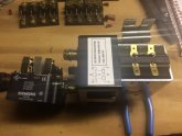
IMG_1357.JPG

Double Pole means two sitches built in.
Double Throw means the switches have two different outlet paths for two different circuits.
DPDT, Two switches with two positions each.

In the case of shutting down things in a fire, NC (No Power) is normal operation,
NO isn't connected to anything, it simply opens the main battery cables to inverters/appliances and all that shuts down.
Once the smoke/fire source is found & corrected, then you simply reset the relay.
 
  • Like
Reactions: Dzl
Well its been on my mind all day and i think i will go with sterling pro latch, the past 2 days since i watched Wills videos i have spent about $1300 just because i'm stuck at home during this lockdown, (That does include LiFePO4 fortune cells) after spending that much whats another $140... Also if i ever decide to change my panels and go 24v then everything will be pretty much compatible just new panels, inverter and another battery and i would be good to go.

I decided on the sterling because it has its own low voltage disconnect built in, but i could always just connect it to the load side of my MPPT SCC and have that manage the low voltage disconnect or even the BMS? These are options i will have to look at next.

The mot important thing for me is current draw, my system is only small with 100ah LiFePO4 battery and 300w solar panels (3x100) which if my calculations are correct should be able to power the day to day running of my shed, which is normally just outside lights and a freezer, i will also install an ATS so if the battery is low then it will switch back to the grid.

Currently i am using a cheap Chinese grid tie inverter which is illegal where i live so this is the main reason i decided to do this project.
 
  • Like
Reactions: Dzl
No reason for relays to be stupid expensive,
Keep in mind electric carts, fork trucks have used big relays for a century...
Lots of applications out there with surplus on the market.

And those golf carts, load bearers, loaders come in all different voltages, so it's not real hard to find the voltage you need...

What I see as a failure of imagination or education is the relay doesn't have to be powered all the time.
*IF* the circuit is designed correctly, for power conservation, the relay is Normally Closed (NC) and doesn't use any power at all, exactly zero until you need it to open.

I put a fire shutdown in my system, never seen fire prevention & supression built into a system,
BUT,
Having seen things go wrong, I built one into my system.
Since I have a BIG HONKIN' Battery right there, when fire detection trips, the NC Relay OPENS with battery power (so it stays open during the fire emergency).

Double Throw, two circuits powered by one source, it's an 'Either/Or' switch.
Either one circuit, OR the other.
Normally Closed (no power) is normal function, everything working fine.
Normally Open (power to close) is your second circuit that normally isn't used.

For me, NO is nothing, goes nowhere.
Just opens the primary circuit to shut down what ever is connected.
It *Could* switch to a backup well pump for instance...
One pump doesn't raise pressure, second pump comes on automatically but takes extra power for the relay,
But you aren't out of water...

Same with two inverters, one 'Normal' (NC),
The second inverter much larger so the extra power drawn by the relay isn't an issue since you are pulling a big load somewhere.
Allows for remote switching from your big power appliance/device.
Switch back to NO (normal operation) when you are done with the big power device.

View attachment 11232

Double Pole means two sitches built in.
Double Throw means the switches have two different outlet paths for two different circuits.
DPDT, Two switches with two positions each.

In the case of shutting down things in a fire, NC (No Power) is normal operation,
NO isn't connected to anything, it simply opens the main battery cables to inverters/appliances and all that shuts down.
Once the smoke/fire source is found & corrected, then you simply reset the relay.

Hey JeepHammer,

The problem i see with NC is it needs power to open, for my instance it would be fine because im sure of the voltage went down to 11v it would keep the relay open for quite some time probably days. However for a safety system that you are using for fire suppression what would happen if the battery used to open the relay was the cause of the fire?

I have always been told its best to design a safety system that does not need power to operate, this is how we operate some safety systems on cruise ships, for example if the ship had a loss of power (it happens could be certain vertical zones or just propulsion etc) the relay would open and automatically mute any music playing in the bars, casino, nightclub so if the captain had to make any announcements over the safety PA no power would be needed to open all the relays across the ship.

I used to be an electrician by trade 10 years ago. Now i work as a fleet technical manger for the largest cruise line in the world ;-)

Anyhow, thanks for the info i did forget about using a NC relay so i will do some searching and see what i can find.

Thanks
 
I used the fire disconnect as an example.
My fire disconnect used an open frame contactor and when the contacts open a mechanical, non-conductive wedge drops into place keeping contacts open until the wedge is removed and system reset.

I'm all about redundancy being off grid, this was a simple, redundant way to use low cost components for a virtually fool proof disconnect.
With non-conductive wedge, pistol magazine spring to push/hold it in place, the contacts are open until two separate manual reset steps are taken...
No way for the system to fail and reset itself.

The normally open contacts trigger fire supression gas release in battery case & combiner/transfer box.
No power to continue fire, no oxygen so existing fire can continue.
Lots of cheap inert gases out there to use, and evacuating oxygen means even superheated slag metal can't resart the fire.
If you use gas with high expansion rate the boxes are also cooled quite well, in testing pretty much everything gets frozen.

For less critical applications, like common switching, NC is the no power option.

Just don't forget it's MUCH better to get a relay with (magnetic) blow out protection.
A magnet between terminals will pull an arc out sideways, often stopping arc over between breaker points.
I've added rare earth magnets to the sides of older contactors from the surplus market, but most of the better contacts will have magnetic blow out protection.

An induction reversion diode between activation coil contacts will stop a crap ton of issues with big coil contactors. A big coil of wire with an intense magnetic field around it will produce inverse current when that magnetic field collapses... It becomes a transformer, like an ignition coil, reverse to the polarity of the coil in normal operation.
The diode kills that issue.

A resistor between primary contact points (high current) stops the "Inrush" or "Surge" issues when breaker points open/close.
Diodes & resistors are stupid cheap and make the more expensive contactor live MUCH longer.
They will also keep the contact points from throwing molten hot copper slag in the event of a plasma arc failure...

You only have to see a plasma/molten copper blowout ONCE before you start to respect the power these relays handle.

We've posted this in a few threads already, and if you look at the picture above, you can see a reversion diode soldered in between positive & negative terminals.
 
Back
Top