diy solar

diy solar

warm breaker, can I increase size above 60a ?

Texican

Solar Enthusiast
Joined
Feb 8, 2022
Messages
516
the breaker that feeds my off grid main panel from the 2 inverters is 60a and has tripped a few times and feels warm/hot to touch
my system is dual MPP LV6548 inverters with 6 eg4 batts
on these hot days I was trying to run 2 mini splits that use 240v and was pulling up to 6000w total to the house

the breaker panel in question is in my workshop with the batts and inverters. the breaker in the panel is a siemens 60a
in the house is a 100a panel with 100a breaker

wires between workshop and house are #4 AL

I will be replacing the 60a breaker in case it is faulty and overheating, wondering if its possible to safely replace with a slightly larger breaker ?

with both mini splits running I think I was pulling maybe 55 amps when breaker trips
Should be #2 AL, or #4 copper...
Wire is overheating the breaker when pulling full load on at least one phase...

Make sure you have the inverters syncing for split phase, not paralleled 120V...
 
How big are the minisplits?
55A from two minis? I'm around 12A with 2 going...
What voltage? Are they sharing a single phase?
 
Before any de rating , the #4 al conductor is only good for 65 amps. I would not exceed the 60 amp breaker size. Make sure you have good connections and use anti ox on the aluminum wire. I would use copper wore
 
with both mini splits running I think I was pulling maybe 55 amps when breaker trips

As is expected. 60A breaker x 0.8 = 48A max continuous.

Breakers do age. A brand new breaker may run cooler and not trip.

If you get a magnetic-hydraulic breaker, it doesn't generate heat from an internal resistance element, and doesn't trip due to heat from terminal & wire.
Midnight/CBI guaranteed not to trip below 105%, guaranteed to trip above 130%.
Carling guaranteed not to trip below 100%, to trip above 125%

I think I prefer magnetic-hydraulic to protect motors. Can handle 5x surge, but trips faster than a thermal breaker in case of locked rotor.

How did you determine 55A? From current measurement, or from watts or VA?
If mini-split has VFD, likely has diode/capacitor front end. That will draw something like 2x the current for 1/2 the time, 4x the heating for half the time, 2x the average heating. Same as steady-state 1.4x the current.

(Which I suspect magnetic-hydraulic won't register, just 1x, so gotta wonder if it protects wires properly!)
 
I am confused on what my limits are/should be with my system
the mini splits are 2 ton each. they are 240v on 20a breakers per specs

I use emporia vue on all circuits. when the units are running at max they show 3000 watts each mini split
if I display amps it shows about 12 amps each = 24 amps, but total system usage shows twice as many amp = 50a
I just realized why that is..... maybe because I only have the emproria ct on 1 leg of the 240v wires
 
on these hot days I was trying to run 2 mini splits that use 240v and was pulling up to 6000w total to the house


with both mini splits running I think I was pulling maybe 55 amps when breaker trips
That math ant mathin....

6000w total /240v = 25a (27a at 220v)

55a@220v = 12,000w your inverters are running at nearly 100% load?
 
Before any de rating , the #4 al conductor is only good for 65 amps. I would not exceed the 60 amp breaker size. Make sure you have good connections and use anti ox on the aluminum wire. I would use copper wore
NO...
Al wire connected to a residential circuit breaker must use the 60C ampacity column.
That shows 55A max... and any continuous use circuit needs 120% capacity
Gotta use #2 AL, or #4 copper...
 
Correct . Wasn't including any derating factors just a " I wouldn't " .
 
the breaker that feeds my off grid main panel from the 2 inverters is 60a and has tripped a few times and feels warm/hot to touch
my system is dual MPP LV6548 inverters with 6 eg4 batts
on these hot days I was trying to run 2 mini splits that use 240v and was pulling up to 6000w total to the house

the breaker panel in question is in my workshop with the batts and inverters. the breaker in the panel is a siemens 60a
in the house is a 100a panel with 100a breaker

wires between workshop and house are #4 AL

I will be replacing the 60a breaker in case it is faulty and overheating, wondering if its possible to safely replace with a slightly larger breaker ?

with both mini splits running I think I was pulling maybe 55 amps when breaker trips
My advice is to start with replacing the breaker and double check good connections (Aluminum has to be perfect). You than want to monitor it for excessive heat and amount of loading. Once you trip a breaker on excess loading it tends to weaken it and make subsequent tripping easier to happen.

Other posters have covered the breaker sizing question.
I think he has figured it out.
He has two 120V loads on a single line from the pair of inverters...
 
Can you provide a code citation supporting this for non-Romex aluminum, large conductor (>#10)?
You have to have a breaker MARKED that it is rated for higher C...
All residential breakers are 60C...
If you have a breaker marked for a higher temp, then you can follow that column on the chart... as long as BOTH ends of the conductor equipment is so marked...
 
You have to have a breaker MARKED that it is rated for higher C...
All residential breakers are 60C...
If you have a breaker marked for a higher temp, then you can follow that column on the chart... as long as BOTH ends of the conductor equipment is so marked...
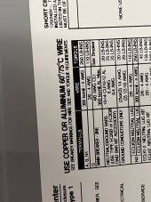
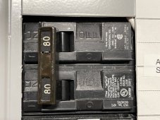
Here are the rating stickers on my residential (well, 120/240 if that means residential) subpanel from Siemens. It looks 75C rated. Most of my two pole GFCI/AFCI breakers are also 75 or 60/75 marked.

The feeder to this subpanel was also done with #1 Al on 75C column back when the house was built

IMG_2080.jpeg
IMG_2079.jpeg
 
Looks good to me.

It isn't an NEC code issue temp rating, it is a connection equipment rating

As long as the equipment on BOTH ends of the wire are so marked, you are good.
 
Also keep in mind, feeder circuits frequently are over rated because of uneven use loads...
A feeder 80A to a subpanel could have 200A of connections on it, but they are seasonal, and sporadic, so there are reduction calculations on the size...
 
My advice is to start with replacing the breaker and double check good connections (Aluminum has to be perfect). You than want to monitor it for excessive heat and amount of loading. Once you trip a breaker on excess loading it tends to weaken it and make subsequent tripping easier to happen.

Other posters have covered the breaker sizing question.
Also, aluminum will loosen connection lugs over time.
Heat cool load cycles will actually back out the lug screws...
Torque them, the retorque them, then annually go back and torque them again...
 
I'm not sure I buy that for all Al connections.

If that was the case for all connections, I would have to call an electrician every year to coordinate a power shutdown to torque the connections inside the meter base up to my service disconnect. Those are all Al connections. The service conductors from POCO up to meter are all Al in my area (POCO rule)

Maybe the ones that have no way to de-energize are made from special alloy with matching thermal expansion coefficient with Al conductors... in that case, the other ones should be too to reduce maintenance (and I've heard that's the way dual rated terminations are supposed to be designed, but I don't have a citation on hand) ?
Your question is a good one. I have not noticed problems with the aluminum main service wires coming loose if properly torqued to begin with. These connect to a bus and not a breaker most often. I have seen issues with aluminum wire feeding breakers working loose with time.
 
Back
Top