diy solar

diy solar

What are good connection point techniques for solid connections

Voltage but I think you've got it!

Hi,

When checking voltage drop is it better to have a larger load like the a microwave or will a smaller load work.

Asking because when running the microwave, it obviously consumes much more battery and will you may notice the change in voltage more due to consumption rather than an actual voltage drop (if that makes sense).
It's easier to spot when the loads are the highest. Anytime I complete a system, make any changes to a system or as part of an annual check up I get the system up to 100% of it's rating, even it means adding a little space heater, then start taking measurements.
 
Not sure the buss bar can handle the current.. Try using 2 wires on the Shunt. 2/0 to inverter on bottom and another wire lug on top of it to buss bar.
Shunt @ 500A is 0.05V. So 0.0001 ohms. Power loss (heat) ohms * current * current, @200A = 4W
 
Last edited:
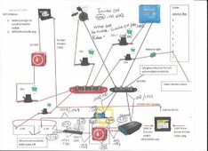
Hi, I was able to check voltage drops. Do these numbers make sense?

This was before doing any changes or inspection of the connection points.

Top or first number was inverter on, but no load.
Second or bottom number is inverter on with microwave (900W) heating water
Circled number was voltage along the circuit with inverter on but no load.


Voltage drop.jpg
 
The voltage drops look OK.
Fuses could use some rework.
1. Class T should be the single battery fuse. Green should be moved from battery to Class T output.
2. I would use better fuses. Higher AIC rating. ANL has good AIC but is large. Midi Fuses are smaller and up to 5000AIC @12v.
Midi Fuse holders
Midi Fuse assortment
tks...I'm a bit fuzzy what you mean by "Green should be moved"

You mean replace all the blade type fuses?
 
tks...I'm a bit fuzzy what you mean by "Green should be moved"

You mean replace all the blade type fuses?
No he's saying the positive wire to the buss bar should be on the other side of the class T. Actually it should be further and past the on/off switch.... So you turn off power to everything.
 
tks...I'm a bit fuzzy what you mean by "Green should be moved"

You mean replace all the blade type fuses?
Yes the blade fuses should be replaced. Did not find an AIC rating for ATC etc.. They tolerate engine compartment temperatures. Fuses blow from overheating, and are self heating. At room temp it might take 60A to blow a 30A blade fuse. That fuse holder you show is typically 12AWG or less.
Victron has an internal LET fast blow fuse. So I put my Midi fuses near the buss bar. Sized 1.25 to 1.33 * the current. 6 AWG for Victron 100/50, 8 AWG for 100/30.

build notes:
Added Electrical
2 LiFePO4 mounted under sink, DIY 200AH and 280AH
1 200A Class T main fuse
1 60A Midi fuse, Yellow, 50A Victron Smart Solar controller for roof mounted
1 40A Midi fuse, Green, 30A Victron Smart Solar controller for ground placed
1 60A Circuit breaker for 250W inverter doubles as On/Off switch.
Notes: Inverter has on/off switch. 8AWG is largest it will take.
Add 12v power line filter (2200mf) to help with surges.
1 battery switch, isolates above from 12v system.
1 40A Midi fuse, Green, 12v Frig fuse, 12v system near ANL fuse
1 80A ANL fuse from battery to 12v system (converter).
1 Victron Smart Shunt on LiFePO4 ground line
AC breaker pair added. Converter wire moved there.
 
Last edited:
No he's saying the positive wire to the buss bar should be on the other side of the class T. Actually it should be further and past the on/off switch.... So you turn off power to everything.

I was keeping the 30 amp circuit seperate from the higher load inverter circuit.

If I move it to the other side of the Class T do I keep the 30 amp fuse?

I'm not sure what moving after the class T accomplishes other than not having directly connected tot he battery. That circuit does not need high amp protection.

TY
 
In keeping with standards the Class T should be the trunk fuse. Simple with less chance of wire shorts. After it are the branches.
A short to/from 30A battery fuse might draw enough current to make the wire glow like a cigarette lighter.
Likewise the DC AIC current could be high enough to sustain an arc in the fuse, a real fire hazard.
Of course the longer the run and the lighter the gauge (higher ohms) the lower the AIC.
 
Last edited:
I kept one lead acid (LA) tongue battery for the trailer brakes. Sticker said LA required. The LiFePO4 BMS could be shut down due to temperature. Also there is no OEM fuse from LA battery to breakaway trailer switch.
I'd rather not have an accident where some lawyer could mislead a jury about modifications.
There is a OEM battery switch that separates the 2 systems (tongue and house).
BTW: That doesn't look right, pin 6 should be vehicle power
 
Last edited:
I was keeping the 30 amp circuit seperate from the higher load inverter circuit.

If I move it to the other side of the Class T do I keep the 30 amp fuse?

I'm not sure what moving after the class T accomplishes other than not having directly connected tot he battery. That circuit does not need high amp protection.

TY
Yes you keep the 30a fuse. The class T protects the wiring from the battery then the 30a fuse protects the wiring from the class T to the load. All downstream. Also keeps the balance of batteries so power flows through it.

Also that 30a is the max load though the buss bar as it is. Might want to upgrade it to a higher amp and wiring like 90 if you have 3 30a devices. Id always want a fuse to protect the buss bar as it's a point of failure and major risk of a short
 
I kept one lead acid (LA) tongue battery for the trailer brakes. Sticker said LA required. The LiFePO4 BMS could be shut down due to temperature. Also there is no OEM fuse from LA battery to breakaway trailer switch.
I'd rather not have an accident where some lawyer could mislead a jury about modifications.
There is a OEM battery switch that separates the 2 systems (tongue and house).
BTW: That doesn't look right, pin 6 should be vehicle power

That's a good thought about keeping a LA battery for the brakes.

When I moved my batteries inside when I went with lithium. One thing I hated when they were on the tongue was if you turned the battery switch off, it also turned the power to the e-brakes off. So if you mistakenly left your battery switch off while traveling, you would have no e-brakes. So if you look at my drawing, I connected the e-brakes directly to the outside junction box. An indicator lights shows if the fuse blows for some reason and there is no power.

That is terminal #6 in a junction box on the tongue. That is where my e-brakes get their power from. But it's also vehicle power.
 
In keeping with standards the Class T should be the trunk fuse. Simple with less chance of wire shorts. After it are the branches.
A short to/from 30A battery fuse might draw enough current to make the wire glow like a cigarette lighter.
Likewise the DC AIC current could be high enough to sustain an arc in the fuse, a real fire hazard.
Of course the longer the run and the lighter the gauge (higher ohms) the lower the AIC.
@Pappion Good points.

So I would tie in the 10AWG wire (to the bus bar) on the output side of the Class T, but before the inverter switch?

TY
 
Yes. I would use at least 8awg, preferred 6awg, since your connecting to converter and fuse box. Odd that it is only a 30A converter. That branch has the most potential to get a short, so AIC is important.
I used 80A ANL fuse on my 60A converter / fuse box branch. ANL is about 6000 AIC at 32v and higher at lower voltage. Midi is 5000 AIC at 12v. No battery bus bar, just two 4awg battery connectors stacked on one end of Class T fuse. Other end stacked 6awg connector to ANL, 2nd connector to Solar controllers Midi fuses and inverter circuit breaker, very short wire runs.
Blue Sea systems fuse and wire chart
 
Last edited:
The voltage drops look OK.
Fuses could use some rework.
1. Class T should be the single battery fuse. Green should be moved from battery to Class T output.
2. I would use better fuses. Higher AIC rating. ANL has good AIC but is large. Midi Fuses are smaller and up to 5000AIC @12v.
Midi Fuse holders
Midi Fuse assortment

@Pappion

I did what you say...but I have a 30 amp charger tied into the positive bus bar (not shown on my drawing).

It blew the fuse..although I only had a 20 amp fuse in the short wire.

In order to use 30 amp. do I just need to upgrade the short wire (and fuse) I moved to say 8 or 6 AWG.

All other DC lines are 10 AWG (excpet invert circuit). They would be good?

Also, would you know why all my victron devices (4 ea) read about 0,1 amp more than the actual battery voltage (measured with meter)

TY
 
Look at the lower part of the blue sea systems, link in my prior post.
Top chart is for % voltage drop for length of AWG. Lower chart to select fuse for AWG
OK, 30A circuit needs a fuse 1.25x to 1.33x higher (40A) to prevent nuisance blows. So you need at a bare minimum 10AWG, 8awg is better.

My new setup uses Victron Smart Shunt and 2 Smart Solar controllers. They form their own wireless network and use the battery voltage data from the Smart Shunt. My Smart Shunt + power wire is connected at the class T fuse output. Move your meter leads around to these points.

If not networked, the Solar controllers will have errors due to wire voltage drop. The higher the current the more the error. Generally the solar controllers battery wiring should have the largest gauge wire their terminals can handle. However, the tinned 6awg I bought was too big of a bundle and the 8awg was easier to fit.

No the 10AWG to the buss bar is not good enough. You surprised me with more victrons. Your converter has 6awg, I would have 6awg mains. Converter to bus bar, bus bar to Class T.

BTW: My old A-frame camper had a 50A converter and a 30A fuse at the battery. Guess the old Lead Acid Batteries charge currents would not blow the fuse. Changing over to LiFePO4 would blow it.
 
Back
Top