You are using an out of date browser. It may not display this or other websites correctly.
You should upgrade or use an alternative browser.
You should upgrade or use an alternative browser.
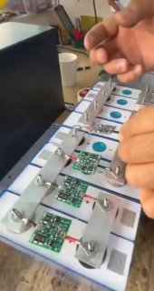
What is this PCB module connected to the positive and negative electrode of the each individual cell? I have never seen anything like this...
- Thread starter BekimV
- Start date
sunshine_eggo
Happy Breffast!
Monitor/balancers, pre-bms era.
These where pretty common on older setups. Those likely just start burning off current above some arbitrary voltage.
The more sophisticated ones had a single signal cable that could engage a control circuit. Each was connected to the next in series. At the ends of the series, those could be connected to a relay or an input. If any of the monitors observed an errant voltage, they could open or close the circuit to trigger some sort of secondary cut off.
Sojourner1
Itinerant
sunshine_eggo
Happy Breffast!
Yep. My experience was with an aftermarket 10kWh plug-in pack for a Gen2 prius.
BekimV
New Member
- Joined
- Jul 10, 2021
- Messages
- 16
Thanks, thats interesting.Monitor/balancers, pre-bms era.
These where pretty common on older setups. Those likely just start burning off current above some arbitrary voltage.
The more sophisticated ones had a single signal cable that could engage a control circuit. Each was connected to the next in series. At the ends of the series, those could be connected to a relay or an input. If any of the monitors observed an errant voltage, they could open or close the circuit to trigger some sort of secondary cut off.
BekimV
New Member
- Joined
- Jul 10, 2021
- Messages
- 16
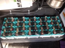
How do they communicate? they only seem to be connected to the + and -. Do they have some kind of bluetooth integrated?Something like this.
View attachment 110625
View attachment 110626
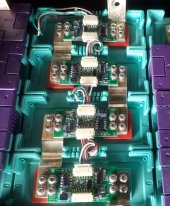
Senseboards that communicate with cpu/ ems.
Sojourner1
Itinerant
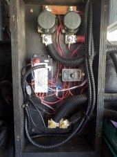
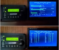
Starting from the 1st cell (left ) they all daisy chain to the last cell 20th. That first senseboard has a connection that goes to the cpu, from there connects to shunt, fuses, solenoids.
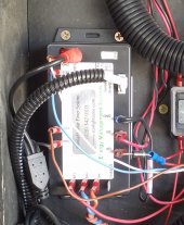
It also has a cable ran into my 5th wheel to a display. The display can be switched to view all cells or see the state of the batteries/ system.
Here are the newer senseboards I put on 2 years ago.

It also has a cable ran into my 5th wheel to a display. The display can be switched to view all cells or see the state of the batteries/ system.

Here are the newer senseboards I put on 2 years ago.

Goboatingnow
Solar Enthusiast
- Joined
- Jul 3, 2022
- Messages
- 1,325
Unlikely they are balancers just look like distributed Bms cell monitors to me
sunshine_eggo
Happy Breffast!
Unlikely they are balancers just look like distributed Bms cell monitors to me
Mine are also balancers as they start burning off somewhere around 3.7V. Little resistors get hot.
Given that the OP's pics have no connections between monitors or other devices, their only function could be balancing.
Goboatingnow
Solar Enthusiast
- Joined
- Jul 3, 2022
- Messages
- 1,325
There must be a connection else they can’t balance either. I see no suitable balancing resistors on these boards so I suspect they are not passive balancersMine are also balancers as they start burning off somewhere around 3.7V. Little resistors get hot.
Given that the OP's pics have no connections between monitors or other devices, their only function could be balancing.
I suspect it is not installed correctly and is doing nothing
sunshine_eggo
Happy Breffast!
There must be a connection else they can’t balance either.
You already corrected yourself in the next sentence.
I see no suitable balancing resistors on these boards so I suspect they are not passive balancers
No one has said "active" balancers until you implied it.
What's "suitable"? I definitely see some things that could be resistors in the OP's blurry picture. "suitable" for passive balancing is often 30-70mA, and I bet they'd fit the bill.
Goboatingnow
Solar Enthusiast
- Joined
- Jul 3, 2022
- Messages
- 1,325
Well unless there is a communications link from each module somewhere it’s not doing either monitoring or balancing.You already corrected yourself in the next sentence.
No one has said "active" balancers until you implied it.
What's "suitable"? I definitely see some things that could be resistors in the OP's blurry picture. "suitable" for passive balancing is often 30-70mA, and I bet they'd fit the bill.
70mA would take forever to balance those cells I suspect especially if severely out of balance
Similar threads
- Replies
- 21
- Views
- 968


