diy solar

diy solar

which would be better-wiring question

mooseandbear

New Member
Joined
Apr 22, 2021
Messages
15
Total newbie here, retired and just want to dabble in solar and wind. My question is- generating area is barn roof for solar and wind power, barn is approx. 100 feet from house. I want all batteries and controllers in the barn due to more space to work. what is best method to get power to house. 1. run # 12 ac lines to house from barn inverter, or 2. put inverter in house and run dc from batteries to house on # 10 wire. nothing fancy and about 2000 watts to start with.
 
Battery voltage being lower will lose far more wattage over distance than ac voltage will.
Always transmit the high voltage the long distance choice.
 
Now, 100’ is a significant distance. Keep in mind voltage drop will also affect the high voltage.
size the wire large enough to minimize the drop.
How many watts are you generating?
#10 may be a better choice even with the high voltage.
 
supervstech has it exactly right... always transmit power as high voltage AC and you should use at least 10awg, get UF-B rated wire.
Of course no idea where you may be, watch out for those local government regulations hehe
 
Run #6's to the house to compensate for voltage drop,
especially if there's a change of upgrade in your mind.
The 2000 watts for now will change real quick once you start having fun.
 
You could further reduce the loss, by buying a European inverter to give you 230V AC for the circuit to the house then use a 230 / 110V transformer to reduce the Voltage at the house end. The transformer will have some losses but you'll probably win overall. A 6 sqmm 3 core armoured cable would do the job nicely - at 230V 2kW is only 8,7 A and you can bury the cable rather than having an ugly overhead circuit. Plenty of room for upgrade, the cable is safe up to 30 A when buried, that's 6.9 kW.
 
finally ready to get started, have 14, 100 watt 12 vt panels and 4 160 watt 12 vt panels. run to house is 125 feet where charger control, inverter and batteries will be located in climate controlled space. A few newbie questions:
1. wire size to house-125' run?
2. best wiring plan for panels, series parallel?
3. best ideas for a combiner box?
4. best ideas for charge controller? size?
5. best ideas for inverter? again size?
6. number of batteries?
My plan is to switch over some circuits in the house that are the vampire loads, small stuff only like tv's on all day, overhead lights, up to 1500 watts of load. Grateful for all help. Finally retired and have the time to work on this.
 
With two different size panels, you should use two different controllers.
With 125' run, you need to use the highest voltage possible... to prevent voltage drop.

1400W
And 640W
What wattage are you needing to run your loads?
 
It is more a question of what can I run with what I have now. NO plans to add more panels, I think 1500 watts will take care of all of the loads. House is very efficient, led lighting, no attempt to run 220vt devices or hvac. My plan is to install system , then turn over all I can to it. I have been monitoring loads and 1500 watts will make a sizeable dent in my power bill.
 
It is more a question of what can I run with what I have now. NO plans to add more panels, I think 1500 watts will take care of all of the loads.
People always tend to under estimate the watts they consume, and over estimate the power panels will produce. So, most likely your plans are going to change whether you want to or not. You'll find out soon.

Most likely, there is not a scenario where you can parallel the 100W panels with the 160W panels for the kind of distance you are working with. 125' is very doable though. That's about what the distance I am running one of my arrays from the controller. To give you a really accurate design strategy, we need to know the specs on your panels. I'll guestimate and say that the 100W panels have a Vmp of 20V and a Voc of 24V, putting out ~5A. The 160W panels might have about the same voltages, but putting out ~8A.

If you have a 200V controller, like an Epever Tracer 5420, you could wire 6 of your 100W panels in series to get a Vmp of 120V, and an open circuit voltage of 144V. At freezing, the Voc will bump up to ~161V. What are your winter lows like? If you wired all 7 in series, you'd get 140Vmp and 188Voc at freezing. Maybe seven in series is too risky for a 200V controller. Midnight and Outback make 250V and 300V controllers respectively, but are far more pricy then Epever.

If you wired 6 panels in series for 144V, you could make two parallel strings of those, 6S2P, for 1200W total. But then you are stuck with 6 panels you can't otherwise use. You can't put the 160W panels in series and place them in parallel with the 100W panels, because that string would only have a Vmp of ~ 80V, and all parallel strings MUST be the same voltage. Another alternative is to put 12 of the 100W panels as 4S3P, and wire the 4 160W panels as a fourth parallel string, but you'd waste two 100W panels, and would have more voltage drop across the 125' distance. The higher voltage option, passing 144V though 10 gauge wire, will have very little voltage drop over a distance of 125 feet.

Normally, you don't want to place different amperage panels in series together, because the lower amperage panel will drag the higher amperage one down to it's level. You have two options here. Buy two more 160W panels so you can wire them all in series together, producing a third string making 8A at ~144V, or wire the four 160W panels in series with the two left-over 100Wers, and just settle for losing 3 amps off of the third string.

That would give you three strings of panels putting out ~5A at 144V, or about 2160W total.

BTW, what system voltage are you planning on operating at? Assuming your panels only output 85% of rated power, that's still 147A when charging at ~12.5V. That is a LOT of amps. With a 24V bank charging at 25V, that's only 74A, and only ~37A charging a 48V bank. A 40A charge controller is going to be way cheaper than a 150A controller.
 
You are correct on the specs on all the panels I have. At this point, nothing is set in stone. I am still working on installing the panels in a ground mount. No other parts have been bought, so open to all ideas.
 
I am still working on installing the panels in a ground mount. No other parts have been bought, so open to all ideas.
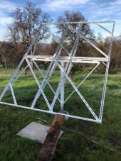
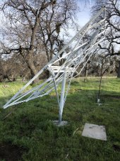
Feel free to copy this design for your use. It's designed for larger high-voltage residential grid-tie style panels, but you could scale it down to your own panels. This can rotate East to West (manually), and also be adjusted for seasonal declination.
 

Attachments

  • IMG_0778 reduced.JPG
    IMG_0778 reduced.JPG
    78.9 KB · Views: 10
  • IMG_0776.JPG
    IMG_0776.JPG
    362.5 KB · Views: 10
What I can tell so far is that,
I will have to break up the system into at least 3 subsystems.
which leads to a question? Can 3 systems feed into the battery bank? 3 charge controllers in, 1 inverter out
it seems to me that after the batteries, it will not make any difference what inverter I have as long as it can handle the output voltage of the battery bank.
 
Sorry, i will have to go back and reread the post from you. My first thought was that it seemed like at lot of amps but I may have not understood where you were going. New to this may take some time to understand. Thanks for the help so far.
 
Sorry, i will have to go back and reread the post from you. My first thought was that it seemed like at lot of amps but I may have not understood where you were going. New to this may take some time to understand.

In this last paragraph what I was referring to is the superiority of higher-voltage battery banks. I was not trying to say you can't do it, I was just trying to say it will be more expensive to do it at 12V.

That would give you three strings of panels putting out ~5A at 144V, or about 2160W total.
BTW, what system voltage are you planning on operating at? Assuming your panels only output 85% of rated power, that's still 147A when charging at ~12.5V. That is a LOT of amps. With a 24V bank charging at 25V, that's only 74A, and only ~37A charging a 48V bank. A 40A charge controller is going to be way cheaper than a 150A controller.


The problem a lot of people have is they get stuck in what's called "the 12V box", meaning they can't conceptualize any solar system that doesn't work at automotive voltage. 12V is really appropriate for the very smallest systems, especially those that operate on DC only. But once you start venturing into the inversion of DC into AC, that's where a higher-voltage bank gives you the advantage. Higher volts is far more easy to handle higher power levels (easy meaning cheaper).

Since your application is a system in barn, starting out with at least 24V makes sense. 48V makes even more sense if your needs exceed ~2000W. This would be easy to accomplish. Just wire two 12V batteries in series, or four 6V batteries, or six 4V batteries. You simply scale the battery size, and hence the string length, to match the correct Amphour rating you need.
 
You are correct, I was thinking 12 vt systems. I will start thinking about a 48 vt system, how many batteries, lead acid will I require? I am thinking at least 10 of 100 amp/hr to make it all work and not continually run them all down too far. Btw: you said something earlier about cold weather, we are in central IN. winter temps. get down to -20 for a few days. Most of the literature I have read does not mention low temperatures because most are written for warm climates.
 
Back
Top