diy solar

diy solar

Will this kiln project damage my inverter?

Aridom82

Learning addict
Joined
Aug 3, 2022
Messages
376
Location
Piedmont (Italy)
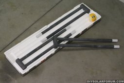
I am building a kiln with sic heating elements, and i am going to power with my inverters. The power will be controlled through pwn duty cycle.
Considering that the inverter is pretty complicated and has to respond in real time to the power demand using different sources, could this switching on and off duty cycle way of controlling the power output potentially damage the inverter? What frequency of the square wave would you use? Could a capacitor big enough help somewhere to smooth it?
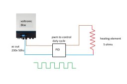
heatingelement.jpg
 
I don't have practical experience with this but I doubt it will be that bad. A high power SMPS like that used in inverter AC is generally considered easy-ish for an inverter, compared with say a single phase motor.

Also laundry dryers have a pretty sharp PWM pattern controlling a high power resistive load (albeit at a lower frequency).

Is this off grid or grid tie / grid assist? In the latter case I doubt there will be much possibility of a problem.
 
Is off grid with batteries, they can use grid power when solar or battery is not avaiable.
If it was a relatively small load i would not mind, but i am going to run this at 75 percent of the capacity of the inverters so it becomes a cause of concern.
 
I agree that a large resistive load is still easier on the inverters than a large induction motor load and we all do that all the time. It may cause brief voltage stability effects for other ac loads which may or may not care.
 
Do it. If it can't handle it, it was junk and you needed to know now rather than later.
 
I would use the slowest frequency that allows good control of the temperature. I would assume that something on the order of 1 Hz or slower should do. You might also choose to limit the duty cycle to maybe 85% to slow the initial warmup and give the inverter a break for a few seconds once a minute or so.
 
I would use the slowest frequency that allows good control of the temperature. I would assume that something on the order of 1 Hz or slower should do. You might also choose to limit the duty cycle to maybe 85% to slow the initial warmup and give the inverter a break for a few seconds once a minute or so.
i was thinking the exact opposite, i thought it would be better for the inverter to have a high frequency and even add a big capacitor to help smooth it.
 
My vote would be for the slower duty cycle since it probably looks more like other large resistive loads that are long cycle PWM modulated, and the high frequency control loop on the inverter's PWM can lock onto the on/off cycles and stay on the appropriate duty cycle for until it switches to off/on. During the transition there would likely be some transients as the inverter PWM locks back on

I guess with the high PWM frequency and capacitor the idea is to make it look more like a constant power device
 
Well, inverters are constantly having to vary their output to maintain proper voltage against a shifting load/resistance, since i would say MOST large inverters are powering circuits which include rapidly varying loads, such as anything that spins, or anything that rectifies AC into DC and them PWMs from that to control something. All of those present rapidly varying load conditions to the inverter. The inverter will handle it just fine. The only side effect i've noticed which doesn't seem to harm anything at all, is that when i am running only an inverter-driven air conditioner and nothing else, my inverters don't seem to calculate load percentage (to report on the screen) well, and it rapidly jumps around by several percent. But, that's just an issue with interpreting a fast signal to report about it to a slow human. It's not a situation which seems harmful to the inverter. Long story short i think you should not worry about this. :)
 
Another possible dimension here is changing the heating element to draw less max power. Presumably the issue here is that the instaneous peak power might be a problem but the average is fine. So bring the two together.

That feels easier than adding a capacitor, but I don't know how your equipment works. Also high frequency switching might need a special SSR or power transformer (is there a frequency dependent switching loss?)
 
Why do you need the inverter? Why not just run DC straight from your battery? If you need more voltage, you could probably make a simple step-up circuit that would use the same mosfet that you would use for pwm.
 
Why do you need the inverter? Why not just run DC straight from your battery? If you need more voltage, you could probably make a simple step-up circuit that would use the same mosfet that you would use for pwm.
I thought about it but this is going to be a kiln/electric foundry very powerfull, +1500 celsius, enough to do cast iron castings. 3 silicon carbide heating elements drawing 12 - 15 kw at max, they can get to 1600 degrees celsius. That would require at 52v +250 amps, is too much. The wires would be massive and the duty cycle switching circuit is going to be difficult. I would rather power them with 3 phase 380v from my 3 inverters. In that way i can keep the amperage down and do the pwm control with hardware not too difficult to find.
kanthalsic.jpg
 
Back
Top