diy solar

diy solar

Wire too big for inverter PV connection

myersfamilyhome

New Member
Joined
Feb 9, 2021
Messages
140
How does one handle properly wiring large gauge PV wire to an CC that has smaller connections?
Scenario :
6x Panels @ 37.07v/13.79a
Distance from Panels to CC: 100ft
EG4 6000EX : PV Connection unspecified (assuming <= 8AWG)
* Not provided in the manual

At this distance, running 15a at 100' require 2AWG. With this in mind and with the CC connections being smaller, how do you properly hookup? Do I run the 2AWG to a disconnect right before the CC and then stepdown the wire to the largest acceptable AWG that will fit in the CC for the remaining few feet?
You don’t need 2 AWG for that run of wire.
14 AWG would be adequate for the current, 12 AWG would get you minimal voltage drop, and 10 AWG would be overkill.
 
Series your panels to increase voltage (37v x 6 = 222V). Are you looking at the wrong voltage curve on the wire chart?

Id use 10/2 UF for that 100ft run @ 222V.
 
You don’t need 2 AWG for that run of wire.
14 AWG would be adequate for the current, 12 AWG would get you minimal voltage drop, and 10 AWG would be overkill.
If panels are in series,
How does one handle properly wiring large gauge PV wire to an CC that has smaller connections?
Scenario :
6x Panels @ 37.07v/13.79a
Distance from Panels to CC: 100ft
EG4 6000EX : PV Connection unspecified (assuming <= 8AWG)
* Not provided in the manual

At this distance, running 15a at 100' require 2AWG. With this in mind and with the CC connections being smaller, how do you properly hookup? Do I run the 2AWG to a disconnect right before the CC and then stepdown the wire to the largest acceptable AWG that will fit in the CC for the remaining few feet?
I agree, critical voltage drop in 100’ is negligible for a 200+ volt run. #10 should be fine.
 
Depends on what you are trying to achieve…
I 100% agree that it very much depends on what you are trying to achieve. But that chart is trying to achieve < 3% or < 10% voltage drop on a 12V system. So 10% is 1.2V and 3% is 0.36V.
This is a 222V system (6*37V), so 3% is 6.6V and 10% is 22.2V. There's a vast difference between achieving a 0.36V drop over 100ft and a 6.6V drop over 100ft.
My answer wasn't meant as a generic: 2 AWG is too much. It was meant as "In this specific application, 2 AWG isn't necessary".
 
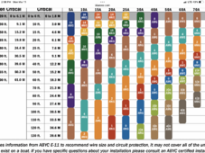
According to many of the charts, even at a 10% loss, 100ft@15amps dc shouldn't be ran on anything smaller than 8AWG and that's leaving no room for growth. Can you help me understand how your coming up with your #'s?
 
According to many of the charts, even at a 10% loss, 100ft@15amps dc shouldn't be ran on anything smaller than 8AWG and that's leaving no room for growth. Can you help me understand how your coming up with your #'s?
Ignore the dc aspect.
Look at the voltage drop. At 222V you lose 5VIMG_2425.png with #12. Negligeable.

Those charts are for BATTERY voltage losses.
 
Look for a voltage drop calculator… not a generic dc chart. Compare apples to apples. You get far better results, and save money!
 
Ignore the dc aspect.
Look at the voltage drop. At 222V you lose 1.2V with #12. Negligeable.

Those charts are for BATTERY voltage losses.
I'm actually looking at the current (amps) aspect. That is more critical and the biggest cause for resistance, heat, and degradation of wires over time.
 
I'm actually looking at the current (amps) aspect. That is more critical and the biggest cause for resistance, heat, and degradation of wires over time.
Which is why we recommend #10 to keep heat to a minimum. But #12 would be under 40C at this distance, and amperage…
 
According to many of the charts, even at a 10% loss, 100ft@15amps dc shouldn't be ran on anything smaller than 8AWG and that's leaving no room for growth. Can you help me understand how your coming up with your #'s?
Low voltage 10% loss is considerably different than high voltage, same amps.
 
I'm actually looking at the current (amps) aspect. That is more critical and the biggest cause for resistance, heat, and degradation of wires over time.
Maybe you could elaborate on what you mean by this?
There are two main things (each of which can have some confounding factors) you need to consider when sizing wire:
1. Ampacity of the wire. Can the wire safely carry the maximum continuous current that you'll send through it without overheating? The overheating part is where people get most confused from what I've seen. Copper can get really hot and still conduct just fine, but the insultation on it degrades or breaks down or melts or burns above a certain temperature, so your cable may have varying ampacity based on the wire size, the insulation material, and even specifics of the installation (i.e., in a packed conduit, the cooling may not be so great). For this part, charts are fantastic! Look up the ampacity of your specific cable, and use that. Ampacity is ampacity: the voltage, whether it's AC or DC, and the distance of the run don't really matter.
But you also need to consider:
2. Voltage drop. Charts exist for this, but they're specific to an application and may be total nonsense for some different application. Best to use a voltage drop calculator and give it the real info (wire size, voltage, current, run length) for what you're trying to do. In general, limiting voltage drop to 3% will give you a conservative answer. But there are definitely cases where you can go beyond 3%, and PV cables are one of them. You sacrifice some power, and that may or may not fit in with your system design, but within reason (say <10%) there really shouldn't be any other consequences. There may even be cases where it would be more economical to spend money on more panels than on more expensive cable.
Agreed. I just now was informed that the panel order has 12x instead of 6x. So that puts me in the ballpark now of 445v@27.58a (6S2P) if I want it to meet the CC requirements. Still doing the run at 100'. With that being said and at a 10% loss, are we saying that running 6awg would be acceptable? If so then I'm still up against the issue of how to properly connect the 6awg to the PV terminals in the CC that are sized 10awg
 
So that puts me in the ballpark now of 445v@27.58a (6S2P)
The voltage shouldn't change from 222V. You still have 6S, so voltage is 6 * 37V = 222V. Current will double though because you now have two in parallel, as you indicate. So now we're looking at 27.6A.
As far as ampacity goes, 10 AWG should be fine for ampacity. Feel free to look up whatever specific cable you're going to use, but 10 AWG should be good for 30A.

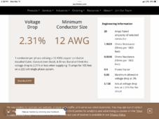
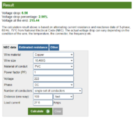
For voltage drop, I use this site, which gives:

1710185070043.png

So 10 AWG would work.

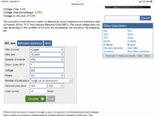
Same result from another site:

1710185186735.png
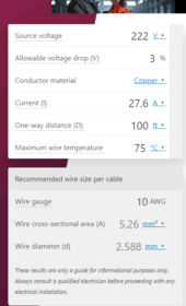
You're still ok with 10 AWG, and under 3% voltage drop. At this point, you're still limited by ampacity to 10 AWG, not voltage drop.
 
You don't size pv circuits for voltage drop, except to determine the economic benefit of wire cost vs. wire losses.

222v/14A use 12AWG. If you want to upsize for future expansion, or you really don't like wire losses, use 10AWG.

8AWG for a single string of panels is just silly.
 
Back
Top