diy solar

diy solar

Chargery BMS News / Update (July-27-2020)

Steve_S

Offgrid Cabineer, N.E. Ontario, Canada
Joined
Oct 29, 2019
Messages
7,791
Location
Rural NE Ontario Canada
Good Day Folks,

I am posting this in ADVANCE as I have been fielding questions in PM and figured I should share what's happening and answer the Q's for everyone, so I thought a small information update is due for the membership here. When the New Manuals etc are posted, I will update the resource section.

Jason has been listening & hearing the input from the BMS users and so things have changed up a bit as a result.
- New 4.1 Owner's Manuals will be out after some corrections this week (I hope). [Just looking at the new drafts now]
- Firmware updates have been done and will be posted as well. (if not already)
- New Shunts have been tested & selected which will now be available.
- New DCC Contactors have been developed by & for Chargery which have some great features that were very needed. sorry I don't know what the pricing will be.
I hope to be able to test the new DCC Contactors soon but it is outside of my hands at this time.

The new Shunts :
new-shunt.JPG
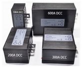
The new DCC Contactors:
DCC-Contactors.JPG

The new DCC-300 showing Big Lug useability.
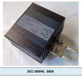
DCC-300A.JPG

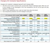
For the Really Curious !
DCC-Specs.JPG
 
These Contactors are interesting but how does this compare on the standby coil mA draw of the DONGYA ones?
 
ATTACHED:
the Dongya DHV Series contact Spec Sheet
the TE/Kilovac EV200 Contactor Series spec Sheet.

the DCC from Chargery is a Solid State - different animal altogether, even has it's own cooling fans +.
 

Attachments

  • DHV200 Engery saving datasheet.pdf
    307.8 KB · Views: 27
  • ENG_CS_EV200_R_TBD_KILOVAC_EV200_Ser_Contactors_0807.pdf
    250.1 KB · Views: 19
ATTACHED:
the Dongya DHV Series contact Spec Sheet
the TE/Kilovac EV200 Contactor Series spec Sheet.

the DCC from Chargery is a Solid State - different animal altogether, even has it's own cooling fans +.
Thanks Steve I need to download these as I keep trying to go back and find them lol.

Yes completely different animal and not sure if I would be able to fit it in my budget or project.

So the Dongya is holding coil @ .16A or 160mA
Chargery is @ .009A - .011A from spec 9mA - 11mA
 
Last edited:
i wish that chargery added the dcc contactors with the kit.totally useless without them
 
Ohhh I cannot speak to pricing, no clue BUT I can tell you that Solid State Relays capable of handling what we use them for are NOT CHEAP. The 500A ones I had made up would come in around $175 for a retail price. NOw what Chargery made is much more than just a relay, it is also a coupler, so you can use ONE relay instead of two. The delay board functions are also built-in as well .

@nwillitts Relays/Contactors are not included because that all depends on the end-use application.
If Separate-Port or Common-Port topology, what amperage needs to be supported for the application and so on. This allows for maximum versatility across different use case applications.

BTW: There is more info which I haven't dropped - I know TEASING...
Jason just sent the new Baseline Docs which I'll edit and update to him within a couple of days and by then hopefully pricing and more will be available for everything. Luckily this edit is not going to be too hard.
 
NEW Chargery 4.1 Manuals, MANY changes and new updates have been added and sent up to Chargery for completion & updating to their site.Sent up July-28th @ 06:00 EST. New Shunts, DCC Smart Relays and more just to tickle our socks into action. Hopefully all updates should be up by end of week July-31. Boy oh Boy they've been busy listening & hearing and implementing the solutions.

No word on price changes or what the pricing is set for the new DCC Smart Relays, I hope that by the time manuals etc are updated on the Chargery Site the new pricing matrix will be available.

FYI, I will be getting a full new Version 4.x BMS8T with 300A DCC Smart Relay for testing & abusing (probably within a couple of weeks I hope) and I will post my experience with that at that time. I may play "swapsies" with one of my production packs just to give it a good whirl, ;-)
 
NEW Chargery 4.1 Manuals, MANY changes and new updates have been added

Thanks, I just had a quick look. One confusing detail still remains:

  • Page 7: "Power Selector: Battery pack to power the BMS. the battery pack must be 4S to 8S LiFe or LiPo or LiTO.
  • Page 24: "2. 2S-3S battery connected to the socket 1 directly, but an external power supply is required"
  • Page 24 (illustration): "2S-4S configuration ext. power required"
    • Chargery BMS8T Manual 4.1 contradiction.jpg
I don't quite get the logic of this. I need to know whether or not a 4S LiFePo battery can power the Chargery BMS8T without an external power supply. According to the first two statements, this is possible, but the text on the illustration contradicts this assumption. Could this be clarified?
 
Well, this is a bit of an issue with the docs and getting things consistent. Part of the issue is battery chemistries and the voltages as well. The BMS requires 15 volts and up to 3A MAX due to driving the relays which are 12V, now of course if the relays draw less power then the BMS draws less.

The chemistries part, LFP for example, in a 4S config can only produce 2.50V min 3.65V max per cell which is 10.00V to 14.6V and that isn't enough to meet the requirements. Now take a 4S LiPo pack at 2.50V min 4.35V max per cell, the pack is 10.0V to 17.4V Max which technically can meet the requirement but the cutoff would be an issue.

The Relays, the major affecting factor, the BMS supports two relays @ 12V up to 3A draw total. This is to support a wide variety of possible options. With the newer Energy Saver Relays and the latest DCC Relay from Chargery which is just about to be released, that power consumption requirement drops as well. This BMS was originally designed for light EV and E-Bikes but made flexible enough for use beyond those two applications and into energy storage systems which have a few other requirements, which are being addressed.

Ultimately, the power requirement for the BMS will be determined by how many and what type of relay(s)/contactor(s) are used and their power consumption.

BTW: I have no affiliation with Chargery Inc, I'm just a satisfied customer, who in the best interest of fellow R.E. enthusiasts, has tried to help pass on the knowledge & help improve a product for the benefit of all of us.
 
Ultimately, the power requirement for the BMS will be determined by how many and what type of relay(s)/contactor(s) are used and their power consumption.

So if I understand correctly, a 4S LFP config may well work if only solid state relays (<= 18mA) are installed?
 
I would hazard a guess that it should work, provided the voltage is sufficient for the relay coil itself per the relay specs. A 12-18V Relay would shut off at 11.5V but a 9-12V relay would not. It also depends on what voltage you have the cutoffs set at, so that the relay will function within the parameters. The new DCC's interconnect with the BMS

I know, a bit muddled, sorry about that but it's already been a long day for me, I'm operating on a 12-hour timeshift and it's crash time for this geezer.
 
LOL I do know the prices but I cant say until I actually have them in my hands for sure. But I was pleasantly surprised. I imagine the Chargery itself will increase a about 5-10 bucks with the new shunts. Especially the 600A version. I will probably stock the 300 Amp versions although the 100 Amp contactor is half the price of the 300 I think for most of us 100 Amps will be too small.
 
I have just ordered one of these for my 16s Lifepo4 bank that will be connected to a AC coupled inverter for battery storage. a) i wasnt aware that it didn't come with the relay despite choosing the 300amp option on checkout, I presume now this is for the shunt value. b) how can this be used with a single relay to manage charge and discharge, is that even possible seeing as my Ac coupled inverter only has one terminal for battery without a separate charge port.
 
@Craig, I seriously doubt the 100A version will be much used by any of us as Shunts should be rated at 125% over what can be expected throughput. Since I've been lurking on this site, I'd have to say the 200-300A range is what most go with. Yes the pricing of the new DCC's will be quite nice from my understanding, actually will make more sense to use those in the end in any case I think.

@shavermcspud , Correct, the BMS8T-300 indicates it is shipped with the 300A Shunt. Relays/Contactors are extra as it depends on your particular requirement & configuration. There are two ways to use a single Relay, 1) is with the new DCC Smart Relay or 2) using a 2 channel Opto-Coupler and one relay acting on both signals, which requires an external 12V source. With your Inverter/Charger the single DC Line coming from it will serve both charge & discharge from the Inverter. The exception of course depends on type of Inverter. Is it just an Inverter, or an Inverter/Charger with AC IN for Charging from the grid or Genset ... all depends.
 
@shavermcspud , Correct, the BMS8T-300 indicates it is shipped with the 300A Shunt. Relays/Contactors are extra as it depends on your particular requirement & configuration. There are two ways to use a single Relay, 1) is with the new DCC Smart Relay or 2) using a 2 channel Opto-Coupler and one relay acting on both signals, which requires an external 12V source. With your Inverter/Charger the single DC Line coming from it will serve both charge & discharge from the Inverter. The exception of course depends on type of Inverter. Is it just an Inverter, or an Inverter/Charger with AC IN for Charging from the grid or Genset ... all depends.
[/QUOTE]


Its an inverter charger AC coupled to add battery storage to an existing solar edge PV system, no genset, just mains coupled with single connection for DC battery source. im not seeing how a single relay and single battery in/out terminal on the inverter can differentiate between charge and discharge
 
Most typically, an Inverter/Charger combo has its own internal switching, which usually handles AC Pass-through as well while charging batteries. With regards to the Relay on the BMS, that is for THE PACK, not the Inverter. The BMS is the last stop protection for the battery cells and will shut-down the pack if an error condition arises. The inverter will have it's own Low Volt & High Volt cutoffs (which should be triggered PRIOR to the BMS forcing it) and charging parameters as well as the normal operating parameters it has to work with. This is called COMMON-PORT Configuration. The Chargery BMS can be used in either Common-Port or Separate-Port, your Inverter/Charger is Common-Port.
 
The inverter doesn’t know if a cell is out of balanced and it is below 2.5V. Only the BMS knows. Clearly, it must be the primary disconnect.

Likewise for charging sources and temperature conditions, the BMS has total knowledge of cell health. Don’t place it in a secondary role.
 
The BMS has the primary role for safety but the inverter LVD has the primary role for normal operation. I guess who has the primary role depends only on the PoV.
 
The BMS has the primary role for safety but the inverter LVD has the primary role for normal operation. I guess who has the primary role depends only on the PoV.

Everything is for the safety of the battery. Charging sources and loads can only assume what’s going on with the battery, while the BMS knows exactly. Who do you want to have control? Someone who’s clueless or someone who has all the facts.
 
Back
Top