I attached diagram so it would be clearer but that what I'm thinkingIf I understand the question--electrically I would think it would probably be the same either way, but I'm not positive. Physically, I'm not sure.


You are using an out of date browser. It may not display this or other websites correctly.
You should upgrade or use an alternative browser.
You should upgrade or use an alternative browser.
Electrodacus Design-Adding Alternator and Inverter/Charger
- Thread starter APhoton
- Start date
Hi, I have not studied up on that yet but my understanding is Aux1 and Aux 2 BUT I NOT 100% SURE!! Aux 1 & 2 are programmable and can be set to turn charger and inverter on and off as needed. I will need to read up, etc. Hopefully someone with more experience can answer that question.@APhoton I want to build a similar system, do you happen to know where EXTIO3 and EXTIO4 are connected to on the Multiplus?
That is clearer, thanks.I attached diagram so it would be clearer but that what I'm thinking
Couple of comments.
You want a 50A breaker between the starter battery and the Victron Orion-TR DC-DC converter. It can draw more than 30A from the starter circuit. I used this Blue Seas 50A self resetting breaker for my system. It will protect the wiring against a short and is designed for tough environments (the engine compartment of a vehicle). I am using 6AWG wiring for my starter power input wiring and that can easily handle a constant 50A flow without a problem. The breaker should be close to the source of the starter current (battery or alternator). That is probably not a place you would not want to put most DC breakers.
Question: Does the Arterra WF-8930/50NPB provide a low voltage disconnect and if it does is it at a threshold that is appropriate for lithium batteries? If not, then you should add a second battery protect on the 12VDC Load output side of the Arterra. If you don't have any 12V loads then ignore this question.
I also don't understand how the 100A shunt and the 300A shunt work together. It looks a bit odd to me, but that is probably because I have never looked at an ElectroDacus system before. In my system I have a BMV-712 measuring battery current and a pair of DC panel meters that measure volts and amps. One for the 24V loads and one for the 12V loads. If I want to see how much solar input I am getting I can read that directly from the Smart Solar (using my cell phone). Different systems do things differently so that is not a knock.
Last edited:
Mex Rider
Solar Enthusiast
- Joined
- Oct 27, 2019
- Messages
- 290
I started with two simple questions related to your thread...sorry it went off topic
We officially forgive ourselves.I started with two simple questions related to your thread...sorry it went off topic

From here on out it is all APhoton.
not a problem. I just know that after awhile these threads build and start to wander all over the place and it's hard for other to get information that helps them. Why don't you start you own thread? Maybe you can transfer your information on this thread to new one?? Not sure how to do thatI started with two simple questions related to your thread...sorry it went off topic
Just add a link there pointing here and one here pointing there so anyone who starts in either can follow what is going on.not a problem. I just know that after awhile these threads build and start to wander all over the place and it's hard for other to get information that helps them. Why don't you start you own thread? Maybe you can transfer your information on this thread to new one?? Not sure how to do that
And we did swerve pretty hard there. Sorry APhoton.
lolWe officially forgive ourselves.
From here on out it is all APhoton.
. No, I think others input is great and desired. I just see too many thread that end up talking about everything and it's difficult for others to get information that they need. I think that this thread should be related to Electrodacus build.Mex Rider
Solar Enthusiast
- Joined
- Oct 27, 2019
- Messages
- 290
All my questions were answered...sorry againnot a problem. I just know that after awhile these threads build and start to wander all over the place and it's hard for other to get information that helps them. Why don't you start you own thread? Maybe you can transfer your information on this thread to new one?? Not sure how to do that
Please don't be sorry. I don't mean to be negative. I enjoy this forum greatly; there's a lot of great people on here and they are extremely helpful and forcing. take care my friend!All my questions were answered...sorry again
As always thanks, I can easily up grade to Blue Sea 7157 Short Stop Circuit Breaker 50 Amps.That is clearer, thanks.
Couple of comments.
You want a 50A breaker between the starter battery and the Victron Orion-TR DC-DC converter. It can draw more than 30A from the starter circuit. I used this Blue Seas 50A self resetting breaker for my system. It will protect the wiring against a short and is designed for tough environments (the engine compartment of a vehicle). I am using 6AWG wiring for my starter power input wiring and that can easily handle a constant 50A flow without a problem. The breaker should be close to the source of the starter current (battery or alternator). That is probably not a place you would not want to put most DC breakers.
Question: Does the Arterra WF-8930/50NPB provide a low voltage disconnect and if it does is it at a threshold that is appropriate for lithium batteries? If not, then you should add a second battery protect on the 12VDC Load output side of the Arterra. If you don't have any 12V loads then ignore this question.
I also don't understand how the 100A shunt and the 300A shunt work together. It looks a bit odd to me, but that is probably because I have never looked at an ElectroDacus system before. In my system I have a BMV-712 measuring battery current and a pair of DC panel meters that measure volts and amps. One for the 24V loads and one for the 12V loads. If I want to see how much solar input I am getting I can read that directly from the Smart Solar (using my cell phone). Different systems do things differently so that is not a knock.
I may try to go without 12v so Victron Energy Orion 24/12 DC-DC Converter 40 Amp Output p/n ORI241240021 & Arterra WF-8930/50NPB Black RV Generator and Component (Distribution Center 30 Or 50 Amp Ac Service - 15 Dc Circuits may be eliminated.
Although I do have a question if I decide to keep 12v devices, input from my inverter & Victron Energy Orion 24/12 DC-DC Converter will have low voltage disconnect via SBMS0 so if low voltage issue with batteries both inverter and converter would be shut down thereby cutting feed to Arterra WF-8930/50NPB.
Two shunts, it's a Electrodacus thing, lol. The 100a is the PV shunt and the 300a is the battery shunt. this is from their manual "The Battery current shunt is mandatory as it is needed to calculate the battery SOC (State of Charge) and gets connected to Battery+ terminal on one side then on the other side to a fuse or circuit breaker and your Load and chargers.The PV current shunt will be great to have as it will provide way more info as with just the battery current shunt mentioned above all you see is battery current and you have no idea of how much the load uses or how much the PV array is producing."
I don't have a full grasp of the finer points, but my understanding is:I also don't understand how the 100A shunt and the 300A shunt work together. It looks a bit odd to me, but that is probably because I have never looked at an ElectroDacus system before.
The Dual shunt concept means the BMS can measure (A) Net current in-out, and (B) total current in which allows it to calculate (C) total current out
There are many potential benefits to being able to see, monitor, and log charge or load current independently. As opposed to just state of charge + net current.
There are other ways to accomplish this I'm sure, but this keeps with the SBMS's centralized command and control model. It allows for 'dumb chargers' to be used, or multiple chargers to be used and still accurately measure total current in either direction (viewable from a single device). The big caveat to this is an inverter/charger.
I think that the Victron Ecosystem with a GX device may have similar functionality (but cost much more and require you stay within the ecosystem, and even in the ecosystem I think that some devices like the Orion-TR may not be compatible). I also do not have a full grasp of Victron's monitoring functionality so I might be missing some details.
I think this should help you with your question. Aux and T-sense need to be configured and used. Configuration is as written in that document except for the last two settings where you will select disable charger.@APhoton I want to build a similar system, do you happen to know where EXTIO3 and EXTIO4 are connected to on the Multiplus?
https://www.victronenergy.com/upload/documents/Manual-Connecting-other-lithium-battery-systems-to-Multis-and-Quattros-EN.pdf
I am a newbie SO Please confirm this. Also let me know if you find anything out
discreetlyspeaking
New Member
- Joined
- Nov 7, 2020
- Messages
- 16
Thanks. Curious about whether you had thought about waiting for the 120V version of the Mulitplus-II.I think this should help you with your question. Aux and T-sense need to be configured and used. Configuration is as written in that document except for the last two settings where you will select disable charger.
https://www.victronenergy.com/upload/documents/Manual-Connecting-other-lithium-battery-systems-to-Multis-and-Quattros-EN.pdf
I am a newbie SO Please confirm this. Also let me know if you find anything out
That is what I was thought might be going on.I don't have a full grasp of the finer points, but my understanding is:
The Dual shunt concept means the BMS can measure (A) Net current in-out, and (B) total current in which allows it to calculate (C) total current out
There are many potential benefits to being able to see, monitor, and log charge or load current independently. As opposed to just state of charge + net current.
There are other ways to accomplish this I'm sure, but this keeps with the SBMS's centralized command and control model. It allows for 'dumb chargers' to be used, or multiple chargers to be used and still accurately measure total current in either direction (viewable from a single device). The big caveat to this is an inverter/charger.
I think that the Victron Ecosystem with a GX device may have similar functionality (but cost much more and require you stay within the ecosystem, and even in the ecosystem I think that some devices like the Orion-TR may not be compatible). I also do not have a full grasp of Victron's monitoring functionality so I might be missing some details.
The Orion-TR Smart Charger does have Bluetooth for monitoring and control, but they still haven't added support for VictronConnect to let the BMV-712 control battery charging. That is why I am using a relay output from the BMV-712 to provide cold temperature charge cutoff to both the Orion and the Multiplus.
In my system I have the BMV-712 measuring battery SOC and manage cold temperature charge cutoff. The Orion-TR and Smart Solar chargers each measure their own charge currents. I can monitor and control all three of these devices with my cell phone. The only thing I can't currently monitor is the Multiplus. I will probably get the Bluetooth dongle for the Multiplus so I can monitor and control my entire system from my cell phone. It seems a bit much to add a GX device just for that when everything else besides the Multiplus has Bluetooth. It has been a learning experience getting up to speed on the Victron ecosystem.
Victron Energy ASS030537010 VE.BUS Bluetooth Smart dongle
Victron VE.BUS Bluetooth Smart dongle is now available in limited quantites
shop.pkys.com
I did add two stand-alone panel meters to the system to give me a way to monitor power consumption in the 24V and 12V loads. These panel meters are really just for my curiosity and piece of mind (I have to look at them to see what is going on, no cell phone monitoring or coordination). These are what I am using. They are dirt cheap, hope they aren't garbage.
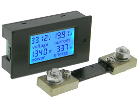
Panel Meter, DC Snap-in, Multi Function DC, 100V, 100A, 10KW
Blue back-lit, Snap-in LCD panel meter with shunt that measures DC Volts, Amps, Watts, Watt hours. Adjustable Overload function (over power alarm threshold: Backlight Flashes.) Ideal for submetering and monitoring. Terminal Strip for Connections & Back Cover. Input Voltage: 6.5-100VDC...
www.mpja.com
It is possible I could measure the 24V load current wirelessly using the Smart Solar since I am using it's load output to provide the low voltage disconnect function for the 24V loads, but I knew I was going to need a panel meter for the 12V loads anyways and I like the symmetry of dual readouts. They will mount on the same control panel as the BMV-712.
I didn't really want to spend the $$$ for an Orion-TR Smart 24/12-30 which adds all the bells and whistles. The other Victron 24/12 DC-DC converters don't have programmable low voltage disconnects or communication so I saw no reason to bother with them. Instead I went cheap with a Uxcell 24V to 13.8V, 40A DC-DC converter and a stand-alone low voltage disconnect PCB. None of my 12V loads are critical so I plan on setting the low voltage disconnect threshold higher for the 12V loads than it is for the more critical 24V loads (refrigerator, lights and fan). That way the system will shed the less important loads first as the battery gets progressively discharged. I will mount the low voltage disconnect modules with the panel meters. It is going to be a really trick control panel.

VHM-009 Battery Low Voltage Disconnect Board | MPJA.COM
Non-isolated, DC voltage disconnect relay module for preventing over discharge of batteries. Adjustable cutoff and reconnect. Relay opens when Input voltage drops below set limit, closes when input reaches the adjustable restart value Rated: 12-36V Batteries Current: 20A max @ 14VDC/125VAC...
www.mpja.com
Man topic swerves just keep grabbing me don't they?
APhoton, how does the Electrodacus handle overall system monitoring? How many different DC loads is it capable of monitoring independently? Would you be able to do the kinds of things I am doing within the Electrodacus or would you need to add more smarts to your system?
I just bought 8 of the 280AH LiFePO4 cells and plan on building a backup Solar Generator system around them. Real reason I got them, is I might loose my nerve about using my DIY LiNMC battery pack in my RV. In that case I will use the LiFePO4 cells instead and use the LiNMC cells for the backup system (which I will not be sleeping over). I plan on building the van battery compartment so it can take either set of cells. The main reason why I am asking is because I am considering using an Electrodacus BMS with the LiFePO4 cells.
Last edited:
Victron moves slow. Might be years before we see this.Thanks. Curious about whether you had thought about waiting for the 120V version of the Mulitplus-II.
Do you know if the Electrodacus can deal with measuring additional charge sources? I have alternator, solar and shore power charging in my system.The Dual shunt concept means the BMS can measure (A) Net current in-out, and (B) total current in which allows it to calculate (C) total current out
Ouch. And this is the cheap one.Thanks. A heat shrink tube printer sounds fantastic! Having a label at each end sounds great....maybe with the destination as the label. I used an electric carving knife to trim and shape foam. Yeah, I struggled with the heat as well. Trying to just work early and late. It is a challenge keeping the electrical installation from eating up more and more space. It took a long time to come up with a small enough A/C distribution center without resorting to din rail components with which I have no familiarity to order online. The logistics and associated costs have been part of my challenge trying to convert the van in México.

K-Sun/Epson LW-PX900 Label Printer
K-Sun/Epson LW-PX900PCD Label Printer Kit * Must use PX style tape Next Generation Industrial Labeling Solution The K-Sun/Epson LW-PX900 label printer is the future of economical and time-saving electronic label, heat-shrink tube, and bar-code printers.
 www.discount-low-voltage.com
OK, self laminating labels will be fine.

2 x 1 1/2 Inch Panduit Self-Laminating Laser Inkjet Labels - 24 Labels
24 Labels Per Sheet | Clear/White | For Cat5e, Cat6 & Cat6a Cable | Polyester |
That is what I was thought might be going on.
The Orion-TR Smart Charger does have Bluetooth for monitoring and control, but they still haven't added support for VictronConnect to let the BMV-712 control battery charging. That is why I am using a relay output from the BMV-712 to provide cold temperature charge cutoff to both the Orion and the Multiplus.
In my system I have the BMV-712 measuring battery SOC and manage cold temperature charge cutoff. The Orion-TR and Smart Solar chargers each measure their own charge currents. I can monitor and control all three of these devices with my cell phone. The only thing I can't currently monitor is the Multiplus. I will probably get the Bluetooth dongle for the Multiplus so I can monitor and control my entire system from my cell phone. It seems a bit much to add a GX device just for that when everything else besides the Multiplus has Bluetooth. It has been a learning experience getting up to speed on the Victron ecosystem.
Victron Energy ASS030537010 VE.BUS Bluetooth Smart dongle
Victron VE.BUS Bluetooth Smart dongle is now available in limited quantitesshop.pkys.com
I did add two stand-alone panel meters to the system to give me a way to monitor power consumption in the 24V and 12V loads. These panel meters are really just for my curiosity and piece of mind (I have to look at them to see what is going on, no cell phone monitoring or coordination). These are what I am using. They are dirt cheap, hope they aren't garbage.
Panel Meter, DC Snap-in, Multi Function DC, 100V, 100A, 10KW
Blue back-lit, Snap-in LCD panel meter with shunt that measures DC Volts, Amps, Watts, Watt hours. Adjustable Overload function (over power alarm threshold: Backlight Flashes.) Ideal for submetering and monitoring. Terminal Strip for Connections & Back Cover. Input Voltage: 6.5-100VDC...www.mpja.com
It is possible I could measure the 24V load current wirelessly using the Smart Solar since I am using it's load output to provide the low voltage disconnect function for the 24V loads, but I knew I was going to need a panel meter for the 12V loads anyways and I like the symmetry of dual readouts. They will mount on the same control panel as the BMV-712.
I didn't really want to spend the $$$ for an Orion-TR Smart 24/12-30 which adds all the bells and whistles. The other Victron 24/12 DC-DC converters don't have programmable low voltage disconnects or communication so I saw no reason to bother with them. Instead I went cheap with a Uxcell 24V to 13.8V, 40A DC-DC converter and a stand-alone low voltage disconnect PCB. None of my 12V loads are critical so I plan on setting the low voltage disconnect threshold higher for the 12V loads than it is for the more critical 24V loads (refrigerator, lights and fan). That way the system will shed the less important loads first as the battery gets progressively discharged. I will mount the low voltage disconnect modules with the panel meters. It is going to be a really trick control panel.
VHM-009 Battery Low Voltage Disconnect Board | MPJA.COM
Non-isolated, DC voltage disconnect relay module for preventing over discharge of batteries. Adjustable cutoff and reconnect. Relay opens when Input voltage drops below set limit, closes when input reaches the adjustable restart value Rated: 12-36V Batteries Current: 20A max @ 14VDC/125VAC...www.mpja.com
Man topic swerves just keep grabbing me don't they?
I just bought 8 of the 280AH LiFePO4 cells and plan on building a backup Solar Generator system around them. Real reason I got them, is I might loose my nerve about using my DIY LiNMC battery pack in my RV. In that case I will use the LiFePO4 cells instead and use the LiNMC cells for the backup system (which I will not be sleeping over). I plan on building the van battery compartment so it can take either set of cells. The main reason why I am asking is because I am considering using an Electrodacus BMS with the LiFePO4 cells.
Great explanation, one day I'm going to take the time to stare at your schematics long enough for it to completely
penetrate my dense skull and read your planning or build thread (if you have one), you've got a lot of good and creative ideas and knowledge (though I still think you have chassis and earth ground symbols confused
).If by deal with you mean accomodate and monitor, then yes. But you don't have the granularity of seeing how much each source is contributing. You will see overall charge current and total net current. So yes, you could measure all three of those charge sources in aggregate, not individually.Do you know if the Electrodacus can deal with measuring additional charge sources? I have alternator, solar and shore power charging in my system.
But as I alluded to above, the big caveat is an inverter-charger. because it only has one set of wires for inverting and charging, net current will still be accurate (so it will still work as well as a battery monitor) but individual charge and discharge readings will be skewed. This is a shortcoming but the SBMS was designed for an off-grid context where there is no shorepower. One solution is to just use a separate inverter and charger, and the SBMS0 is designed to work with cheap and simple meanwell style power supplies (since control/logic resides with the BMS) or traditional battery chargers.
All loads will be measured in aggregate, so you can add as many differences loads as desired and it will measure them accurately without additional components, but you will not have the granularity of being able to see current for specific loads.APhoton, how does the Electrodacus handle overall system monitoring? How many different DC loads is it capable of monitoring independently? Would you be able to do the kinds of things I am doing within the Electrodacus or would you need to add more smarts to your system?
One more consideration is that Victorn products and the electrodacus dovetail quite nicely. While they don't communicate they do work quite well together and the SBMS can control most Victron equipment, so for those of us obsessed with data and micro managing and customizing, the marriage of the two is appealing (though there are a lot of redundancies in that case).
What specifically do you mean by "would you be able to do the kinds of things I am doing?"
One other shortcoming, it has builtin low temp disconnect but it has only one configurable global limit, you cannot configure charge and discharge temperatures differently. Dacian is pretty adamant that you never want your batteries dropping below zero and that the proper solution to low temps is designing your system so that the batteries never drop below freezing, through insulation, through small heaters, through location or thermal mass. While I understand his argument, and agree with it, I don't think its a good reason not to allow separate cutoff temperatures. But its not a dealbreaker for me.
Similar threads
- Replies
- 15
- Views
- 574
- Replies
- 3
- Views
- 138
- Replies
- 10
- Views
- 967
- Replies
- 44
- Views
- 2K
- Replies
- 38
- Views
- 988