diy solar

diy solar

Electrodacus Design-Adding Alternator and Inverter/Charger

I don't consider a fuse block Daisy chaining because the fuses are connected by short bus bars, like a circuit breaker in a house. Daisy chaining is where you run wires to a load, then run wires from that load to the second load.

I think the alternator charging ground is ok as long as you have a positive and negative wires connecting the alternator to the Kisae, and positive and negative wires connecting the Kisae to the house battery.

The Victron Orion TR comes in both an isolated and a non-isolated version. Even though I think it is not a problem I am using the isolated version of the Orion. I am already spending so much on my RV's electrical system that spending $40 more for isolated version is not worth thinking about.
Thanks....sorry so dumb, but what is the Orion TR? And yeah, I feel your pain on the electrical system budget...ouch!!
 
Victron Orion-TR is a DC-DC (battery to battery) charger for charging from the alternator.

Rotated and enhanced (hopefully a bit easier to read):
t0fpPuo.jpeg
 
I don't see the BMV712 shunt wired in the house battery negative nor do I see the BMV-712 positive connected to the house battery positive.

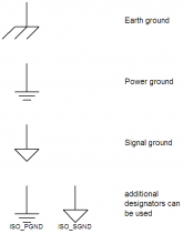
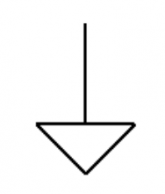
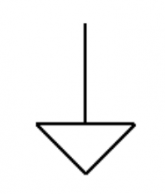
Rather than trying to show the negative return wires which really complicates the drawing, you might try to focus on showing how power flows from one component to another. It can help to start with the house positive bus in the middle and show each chain connecting individually to the DC bus. It is ok to just show a DC negative bus connection as using the common signal, with the understanding that all of the DC negatives end up back at the DC negative bus. I hate to use the term ground, because ground means something different than just the DC negative bus. I often use the term common and tend to use the signal ground symbol rather than the power ground symbol because I design signal processing equipment rather than power equipment.

Grounds.png

Examples of a chain would be:
  • Solar panels to SCC to bus.
  • Shore power to Victron to Bus

As an example, here is my latest RV electrical diagram. It is complicated, but I hope you get the idea what I am trying to say by showing how power flows. A picture is supposed to be worth a 1000 words. I like to talk so you will probably get the 1000 words anyways, but hopefully getting both will be educational.
 

Attachments

  • VanPower11.pdf
    321.4 KB · Views: 17
Thanks....sorry so dumb, but what is the Orion TR? And yeah, I feel your pain on the electrical system budget...ouch!!
Not dumb at all. Here is a list of several.


Here is the particular alternator charger I am using with my 24V battery. It comes in either an isolated or non-isolated versions. The cost difference is about $40.

 
What specific types of information are you looking for?

Victron Wiring Unlimited is the closest thing to an intermediate level comprehensive book that I am aware of. But I have loooots of specific recommendations depending on what you are looking to learn about. Sometimes I feel a bit like the forum librarian :) I'm not the smartest, most knowledgeable, or most experienced here, not by a long shot, but I'm pretty good at finding information, and have developed a pretty decent breadth of knowledge, so I like helping match people up with the info they seek (particularly because often they can understand it deeper than I have, and teach me something new)

If you look in the resources section of the forum, I have added a lot of the resources that I lean heavily on, FilterGuy Also has some great resources.

I also have a thread where I organize the resources I have found useful, though most of the resources are from much earlier in my learning process

Of note are:
  1. Victron Wiring Unlimited
  2. ABYC marine electrical code (this is the most DIY friendly code I have found)
  3. The Magnum and Samlex Inverter Manuals (I don't own either but I use both documents as references, specifically for grounding related questions)
  4. The near-comprehensive introductory articles on LFP in my signature from Nordkyn and Marinehowto (and the shorter article by Solacity)
  5. Videos by Pacific Yacht Systems for general marine electrical design and AltE store solar information at the beginner to intermediate level
  6. This video on circuit protection as well as this powerpoint
  7. A great video explaining the basics of electricity on a conceptual level, this video is what made a lot of things finally 'click' for me
  8. RSD Academy videos and articles on grounding and voltage (among other topics)
  9. Videos or Articles by Mike Holt on grounding etc, in the context of the NEC

But based on what you are looking to learn I might have other recommendations.
Thanks this is fantastic! Sometimes I don't know what I don't know i.e. "Marine code (which I often use as a reference wants main battery fuse within 7 inches, or within 72 inches if it is protected in conduit/sheath/etc." so I like to read up on as much as possible
 
I don't see the BMV712 shunt wired in the house battery negative nor do I see the BMV-712 positive connected to the house battery positive.

Rather than trying to show the negative return wires which really complicates the drawing, you might try to focus on showing how power flows from one component to another. It can help to start with the house positive bus in the middle and show each chain connecting individually to the DC bus. It is ok to just show a DC negative bus connection as using the common signal, with the understanding that all of the DC negatives end up back at the DC negative bus. I hate to use the term ground, because ground means something different than just the DC negative bus. I often use the term common and tend to use the signal ground symbol rather than the power ground symbol because I design signal processing equipment rather than power equipment.

View attachment 26996

Examples of a chain would be:
  • Solar panels to SCC to bus.
  • Shore power to Victron to Bus

As an example, here is my latest RV electrical diagram. It is complicated, but I hope you get the idea what I am trying to say by showing how power flows. A picture is supposed to be worth a 1000 words. I like to talk so you will probably get the 1000 words anyways, but hopefully getting both will be educational.

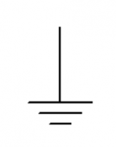
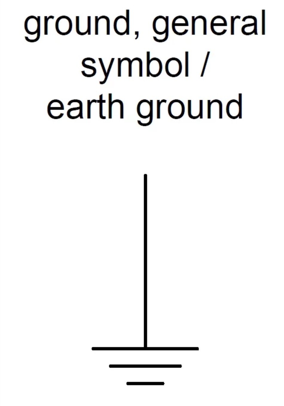
I hope that I have this right! So in your diagram you use this symbol 1604805790198.pngto indicate wire to chassis. And you use this symbol 1604805980123.png for wire going to neg. busbar.
 

Attachments

  • 1604805900730.png
    1604805900730.png
    8.5 KB · Views: 0
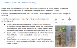
It is my understanding that the image above gets chassis and earth ground backwards, while I'm not a voice of authority on this, I do have a few references to support this (One, Two). Am I misinterpreting something?

Though it seems in practice, at least informally, the symbol for earth-ground
1604805790198.png
is often used as a general symbol for ground (whether chassis or earth) or at least that is what I have observed anecdotally
 

Attachments

  • Screenshot_2020-11-07 Wiring-Unlimited-EN pdf.png
    Screenshot_2020-11-07 Wiring-Unlimited-EN pdf.png
    323.4 KB · Views: 3
Last edited:
I don't see the BMV712 shunt wired in the house battery negative nor do I see the BMV-712 positive connected to the house battery positive.

Rather than trying to show the negative return wires which really complicates the drawing, you might try to focus on showing how power flows from one component to another. It can help to start with the house positive bus in the middle and show each chain connecting individually to the DC bus. It is ok to just show a DC negative bus connection as using the common signal, with the understanding that all of the DC negatives end up back at the DC negative bus. I hate to use the term ground, because ground means something different than just the DC negative bus. I often use the term common and tend to use the signal ground symbol rather than the power ground symbol because I design signal processing equipment rather than power equipment.

View attachment 26996

Examples of a chain would be:
  • Solar panels to SCC to bus.
  • Shore power to Victron to Bus

As an example, here is my latest RV electrical diagram. It is complicated, but I hope you get the idea what I am trying to say by showing how power flows. A picture is supposed to be worth a 1000 words. I like to talk so you will probably get the 1000 words anyways, but hopefully getting both will be educational.
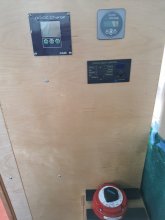
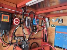
First, thanks for all your effort at education, really is appreciated. I was a better than average draftsman before computers but don't currently have access to the tools, all of which of course have been supplanted by CAD. Second, thanks for calling my attention to the fact I did not label the BMV 712 shunt in the upper left quadrant beneath the PV panels. All the appropriate wiring is there, just not the shunt label. Your design is very clear and if I still had the ego of my youth, I would be jealous, great job! I will tell you that my cumbersome drawing has helped me build the system without forgetting anything (so far) and allowed me to use it like a map, which obviously your system will allow you to do also and in a format you are very accustomed to looking at. I have not drawn my A/C power domain yet and will use the tools you have so graciously provided. The inverter is installed with the DC side wired and the A/C design is in my head and parts ordered but I will draw it before building it to make sure my bases are covered. Wiring the A/C side and then returning the batteries to the van will more or less complete the job, short of completing more of the build and getting in the propane stove and heating systems as well as plumbing, all of which will require more circuits into the DC load center.
 

Attachments

  • front panel.jpg
    front panel.jpg
    75.4 KB · Views: 12
  • electrical panel.jpg
    electrical panel.jpg
    100.5 KB · Views: 12
  • solar panels.jpg
    solar panels.jpg
    198.9 KB · Views: 12
First, thanks for all your effort at education, really is appreciated. I was a better than average draftsman before computers but don't currently have access to the tools, all of which of course have been supplanted by CAD. Second, thanks for calling my attention to the fact I did not label the BMV 712 shunt in the upper left quadrant beneath the PV panels. All the appropriate wiring is there, just not the shunt label. Your design is very clear and if I still had the ego of my youth, I would be jealous, great job! I will tell you that my cumbersome drawing has helped me build the system without forgetting anything (so far) and allowed me to use it like a map, which obviously your system will allow you to do also and in a format you are very accustomed to looking at. I have not drawn my A/C power domain yet and will use the tools you have so graciously provided. The inverter is installed with the DC side wired and the A/C design is in my head and parts ordered but I will draw it before building it to make sure my bases are covered. Wiring the A/C side and then returning the batteries to the van will more or less complete the job, short of completing more of the build and getting in the propane stove and heating systems as well as plumbing, all of which will require more circuits into the DC load center.
You are doing a great job in the installation. The electrical bay is very neet and tidy. I haven't started installing my electrical system yet. I have been collecting components as elements of the design get firmed up. Right now my electrical system consists of a concept, a drawing and a mound of boxes in my office.

Once I get done shaving the excess foam insulation from the walls an ceiling, I will start creating a wiring layout and assign a wire label to each wire. That wiring version will show every wire including all the return wires. I think I will get a heat shrink tubing printer so that every wire will be labeled at each end.

I design electronic equipment for a living so I know exactly what I want the end result to be.
 
The original owner of my Van sprayed the cargo section with closed cell foam insulation. It is a cargo van and they didn't care what it looked like. There is a lot more foam than needed. I appreciate the fact it doesn't get nearly as hot back there, but trimming back the extra insulation so I can install panelling has been an ordeal. I tried a hot knife first (bad idea), now I am using an oscillating saw. It works, but is really slow going. This summer was so brutal I didn't get anything done back there. Going to finish up this winter while it is comfortable.
 
It is my understanding that the image above gets chassis and earth ground backwards, while I'm not a voice of authority on this, I do have a few references to support this (One, Two). Am I misinterpreting something?

Though it seems in practice, at least informally, the symbol for earth-ground
1604805790198.png
is often used as a general symbol for ground (whether chassis or earth) or at least that is what I have observed anecdotally
That symbol is normally used for power ground (ground is a terrible choice of a name for that) and the symbol with a flat top and angled vertical lines is called chassis ground or earth ground.
 
The original owner of my Van sprayed the cargo section with closed cell foam insulation. It is a cargo van and they didn't care what it looked like. There is a lot more foam than needed. I appreciate the fact it doesn't get nearly as hot back there, but trimming back the extra insulation so I can install panelling has been an ordeal. I tried a hot knife first (bad idea), now I am using an oscillating saw. It works, but is really slow going. This summer was so brutal I didn't get anything done back there. Going to finish up this winter while it is comfortable.
Thanks. A heat shrink tube printer sounds fantastic! Having a label at each end sounds great....maybe with the destination as the label. I used an electric carving knife to trim and shape foam. Yeah, I struggled with the heat as well. Trying to just work early and late. It is a challenge keeping the electrical installation from eating up more and more space. It took a long time to come up with a small enough A/C distribution center without resorting to din rail components with which I have no familiarity to order online. The logistics and associated costs have been part of my challenge trying to convert the van in México.
 
That symbol is normally used for power ground (ground is a terrible choice of a name for that) and the symbol with a flat top and angled vertical lines is called chassis ground or earth ground.
This conflicts with my understanding, can you point to a resource that reflects your understanding of these symbols, I would like to understand where the discrepancy between our understandings is coming from.

My understanding is:

Ground (Earth) =
Davis_ground_9.jpg


Ground (Chassis/Frame) =

Davis_ground_12_.jpg


Some References:
https://www.allaboutcircuits.com/technical-articles/an-introduction-to-ground/
https://www.victronenergy.com/uploa...[{"num":570,"gen":0},{"name":"XYZ"},47,806,0]
https://en.wikipedia.org/wiki/Electronic_symbol#Grounds

I believe these are "IEC" symbols (maybe the symbols are different in different contexts or different countries)
 
@Dzl and @HaldorEE Reviewing my Electrodacus plan and going over details. Question: I have wiring going from PV to DSSR20 to a positive busbar ( ¼” x 1½”x 3”; 5/16” bolts/ washers/nuts Copper Rectangle Bar 110-H02) then to 50a breaker attached to pv shunt. Do I need this positive busbar or can I connect two wires from DSSR20 directly to breaker?
 
This will probably be impossible to read unless maybe enlarged on a cell phone. Thanks for your consideration... as alwaysView attachment 26990
@Dzl @HaldorEE should this not go on separate thread? It does not appear this is a review or related to Electrodacus build. Mex that way you will have a separate thread all related to you specific build. I used words to draw my plan if that helps.
 
  • Like
Reactions: Dzl
@Dzl and @HaldorEE Reviewing my Electrodacus plan and going over details. Question: I have wiring going from PV to DSSR20 to a positive busbar ( ¼” x 1½”x 3”; 5/16” bolts/ washers/nuts Copper Rectangle Bar 110-H02) then to 50a breaker attached to pv shunt. Do I need this positive busbar or can I connect two wires from DSSR20 directly to breaker?
@APhoton I want to build a similar system, do you happen to know where EXTIO3 and EXTIO4 are connected to on the Multiplus?
 
@Dzl @HaldorEE should this not go on separate thread? It does not appear this is a review or related to Electrodacus build. Mex that way you will have a separate thread all related to you specific build. I used words to draw my plan if that helps.

You are correct, sorry. I'm easily distractable and half the time don't even know what thread I'm commenting in :rolleyes:
 
Question: I have wiring going from DSSR20 to a positive busbar, then to 50a breaker attached to pv shunt. Do I need this positive busbar or can I connect two wires from DSSR20 directly to breaker?
If I understand the question--electrically I would think it would probably be the same either way, but I'm not positive. Physically, I'm not sure.
 
Back
Top