It does.I decided to add 24v connections for appliances as you did. It was not as straight forward as I first thought since SBMS0 needs to be able to turn them on/off when batteries are discharged to certain level. For this reason I added Victron Energy Battery Protect 12/24-Volt 65 amp and run EXTI5 through 4-Channel Optocoupler. I hope this makes senses


You are using an out of date browser. It may not display this or other websites correctly.
You should upgrade or use an alternative browser.
You should upgrade or use an alternative browser.
Electrodacus Design-Adding Alternator and Inverter/Charger
- Thread starter APhoton
- Start date
Thanks! I'm also considering adding filter and surge protection as you have in your drawing. I had bad experience not having surge protection with a pool pump; cost me a lot of moneyIt does.
Last edited:
I believe you can do it this way (and there are some benefits to doing so) but you do not have to. Generally I think EXTIO3 can be used for multiple discharge control devices and EXTIO4 can be used for multiple charge control devices.I decided to add 24v connections for appliances as you did. It was not as straight forward as I first thought since SBMS0 needs to be able to turn them on/off when batteries are discharged to certain level. For this reason I added Victron Energy Battery Protect 12/24-Volt 65 amp and run EXTI5 through 4-Channel Optocoupler. I hope this makes senses
So your inverter for 120v, your battery protect for 24v and your dc-dc converter for 12v can all be controlled by EXTIO3. At least that is my understanding.
On the other hand if you want to specify different parameters for different chargers or load control devices (which could be really handy) EXTIO 5 & 6 could prove very useful.
I'm not knowledgeable enough to say whether your right or wrong. It seems to me that it sounds correct. The reason I did it this way was Dacian had suggest and I seen it on their forum. Myself I don't know why you just can't splice the wire and go to two or three devices. But the Optocoupler is only $6 (I hope that I did just reveal has stupid I am-lol)I believe you can do it this way (and there are some benefits to doing so) but you do not have to. Generally I think EXTIO3 can be used for multiple discharge control devices and EXTIO4 can be used for multiple charge control devices.
So your inverter for 120v, your battery protect for 24v and your dc-dc converter for 12v can all be controlled by EXTIO3. At least that is my understanding.
On the other hand if you want to specify different parameters for different chargers or load control devices (which could be really handy) EXTIO 5 & 6 could prove very useful.
went back and read what Dacian said "It seems you used all 4 of the EXT IOx so you will need to multiply them externally by adding more optoisolators in order to control all your charge sources and all loads." He does that specify 3, 4, 5 or 6. But if 5 and 6 are available why not use them, as you suggested I can set different parameters if needed/wanted??I'm not knowledgeable enough to say whether your right or wrong. It seems to me that it sounds correct. The reason I did it this way was Dacian had suggest and I seen it on their forum. Myself I don't know why you just can't splice the wire and go to two or three devices. But the Optocoupler is only $6 (I hope that I did just reveal has stupid I am-lol)
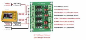
I reviewing 16 pin connector on Electrodacus web sit and came across this. Interesting and I see they add resistors. I need to study this more-do I need resistors??I believe you can do it this way (and there are some benefits to doing so) but you do not have to. Generally I think EXTIO3 can be used for multiple discharge control devices and EXTIO4 can be used for multiple charge control devices.
So your inverter for 120v, your battery protect for 24v and your dc-dc converter for 12v can all be controlled by EXTIO3. At least that is my understanding.
On the other hand if you want to specify different parameters for different chargers or load control devices (which could be really handy) EXTIO 5 & 6 could prove very useful.
Attachments
I believe Dacian's original design (and usual advice) was for the default to be EXTIO 3 and 4 controlling charge and discharge with 5 & 6 being additional auxiliary connections for you to optionally use however you saw fit (including in the way you are planning to). With the new version of the SBMS0 this will still be the default but it will become substantially easier to use extio 5 & 6I'm not knowledgeable enough to say whether your right or wrong. It seems to me that it sounds correct. The reason I did it this way was Dacian had suggest and I seen it on their forum. Myself I don't know why you just can't splice the wire and go to two or three devices. But the Optocoupler is only $6 (I hope that I did just reveal has stupid I am-lol)
The major impediment to this in the past was that the SBMS0 was not setup to utilize EXTIO 5 & 6 out of the box, it required soldering and/or an add on board, I can't remember which or if it was both.went back and read what Dacian said "It seems you used all 4 of the EXT IOx so you will need to multiply them externally by adding more optoisolators in order to control all your charge sources and all loads." He does that specify 3, 4, 5 or 6. But if 5 and 6 are available why not use them, as you suggested I can set different parameters if needed/wanted??
But I believe with the new version of the SBMS0 EXTIO 5 & 6 will be made available in the same way as 3 & 4 which is great, since it makes it much easier to utilize these two additional EXTIO connections.
I see no reason why you shouldn't use EXTIO 5 for DC loads if you want to control it separately from the Inverter, it definitely makes your system more flexible and tweakable. This is probably what I would do as well unless I had other uses for the extra EXTIO's
Many products are designed to punish their customers if they don't do things exactly right. I have learned to be cautious.Thanks! I'm also considering adding filter and surge protection as you have in your drawing. I had bad experience not having surge protection with a pool pump; cost me a lot of money
I designed a galvanically isolated, bidirectional 24V, discrete I/O port for an industrial instrument product 3 years ago. The product it was replacing had discrete inputs and outputs (on separate pins) and they were a major source of failures. Customers would miss wire the I/O circuits and smoke the board. Nobody was happy about this, us or our customers.
The official requirement was for the product to have 24V discrete inputs and outputs that could be used to signal status information to the customer or external equipment or to control operation of the device by means of switches or being connected to PLC outputs. My own criteria for this circuit was that each I/O pin had to be galvanically isolated, be able to operate with or without an external power supply connected. Each I/O pin had to be configurable in software as either an input or and output (on the fly if desired) and the I/O pins had to be completely bullet proof.
When configured as an input, you can short the input to common (GND) and the input will see this is a low input. If you open the switch (to let it float) or connect the input to a positive supply > 12VDC, the input will see this as a high input. When configured as an output, it will source 24V with sufficient current to turn on a high true PLC input (the standard for what that means is output voltage > 15V at 3 mA) and it is also able light an indicator lamp or turn on a relay by outputting a low true (common grounded) signal that can sink up to 100 mA at 24V.
My definition of miss wiring includes wiring an input as an output or vise versa. Connecting the I/O to a reversed polarity DC supply and surviving being connected across 120VAC continuously. To date we have never had one of these input/output ports fail, either in testing or in the field. I think this means our customers must have become a lot more careful in how they use our devices than they used to be.
I have never seen any other commercial product with I/O that can do this. When you buy a PLC they have input cards and they have output cards and one is not the other. That offended me so I set out to do it differently. I am glad I was able to figure out a way to do so.
That long story gives you, I hope, some idea of how I go about designing a system.
-Edit-
This is the device I am referring to. I designed the electronics and wrote most of the firmware that operates it. It contains three ARM processors, uses wireless digital communication and wireless power transmission (inductive). The sensor is designed to measure torque and temperature in a rotating shaft while spinning up to 20,000 RPM and there are no batteries or electrical contact between the rotating sensor and the base station that communicates with it.
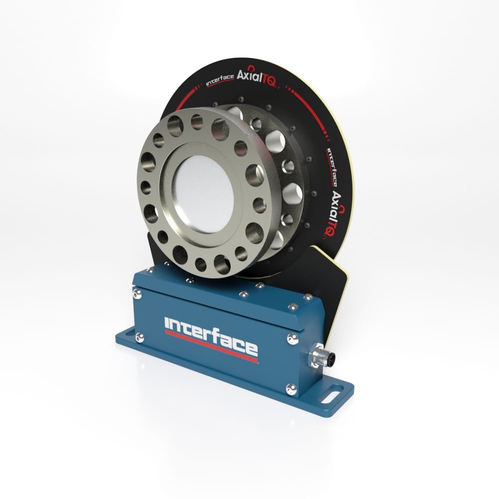
AxialTQ Wireless Rotary Torque Transducer
The Interface AxialTQ™ torque measurement system was developed in direct collaboration with over 30 end-users who shared their wish-lists for operational priorities, user interface, design, features, real-world field issues and more.
 www.interfaceforce.com
Last edited:
@Dzl and @HaldorEE are you able to look at my previous post? If you can I would appreciate it. Either way thanks to both of you for all your assistance.Do my SBMS0 EXTIOx wire connections and types look correct?
Also, I'm considering getting rid of 12v side; just going with 110v and 24v. This was I could do away with 24/12 DC converter.
Attachments
unfortunately Peter at PKYS INC Marine Electrical Systems Experts was not able to review since he cannot advise on items that he does not sell.Another resource is Peter Kennedy at PKYS in Annapolis MD. He is a Victron and Blue Sea dealer as well as a certified marine electrician. He has excellent prices from what I can tell.
I really like his circuit breaker and switch gear panels. Top notch equipment. I am happy with what I ordered from him.
I haven't stared at your schematic long enough to feel I have a solid understanding of the system, but I do have a few thoughts:
- It looks like it is well designed, thought through and detailed. Good job.
- I like your use of EXTIO 5&6 in your design, gives you a bit more granularity
- If I'm reading the diagram correctly you have a substantial bit of unfused wire (4ft) before your first overcurrent protection. Marine code (which I often use as a reference wants main battery fuse within 7 inches, or within 72 inches if it is protected in conduit/sheath/etc. This is a design limitation of the SBMS (not permitting a fuse between the shunt and B+)
- A mega fuse is maybe not the best option for the main battery circuit overcurrent protection. For the main circuit overcurrent protection (first OCP device in a circuit after the battery), for a 12-24V battery marine code wants a fuse that can interrupt >5000A, (this is known as an AIC rating). Looking at Blue Sea's inventory, this would be Class T (20,000A), ANL (6,000A), MRBF (5,000).
- Grounding, review the inverter documentation (I like a lot of things about Victron but the quality of their doumentation and clear safety advice is not one of those things), It is likely you should have an equipment grounding connector between the inverter case GND and the negative busbar or designated chassis-grounding point.
Thanks so much for the positive feedback!I haven't stared at your schematic long enough to feel I have a solid understanding of the system, but I do have a few thoughts:
I have not installed the SBMS0 before, so I can't give you specific guidance on the EXTIO connections.
- It looks like it is well designed, thought through and detailed. Good job.
- I like your use of EXTIO 5&6 in your design, gives you a bit more granularity
- If I'm reading the diagram correctly you have a substantial bit of unfused wire (4ft) before your first overcurrent protection. Marine code (which I often use as a reference wants main battery fuse within 7 inches, or within 72 inches if it is protected in conduit/sheath/etc. This is a design limitation of the SBMS (not permitting a fuse between the shunt and B+)
- A mega fuse is maybe not the best option for the main battery circuit overcurrent protection. For the main circuit overcurrent protection (first OCP device in a circuit after the battery), for a 12-24V battery marine code wants a fuse that can interrupt >5000A, (this is known as an AIC rating). Looking at Blue Sea's inventory, this would be Class T (20,000A), ANL (6,000A), MRBF (5,000).
- Grounding, review the inverter documentation (I like a lot of things about Victron but the quality of their doumentation and clear safety advice is not one of those things), It is likely you should have an equipment grounding connector between the inverter case GND and the negative busbar or designated chassis-grounding point.
3. thanks, there is no reason why I could not shorten that 4'. to 1/2' or less. For all practical purposes, I could attach shunt directly to battery and other side of shunt directly to cut off switch and busbar
4. Will change to MRBF (5,000) that way I can mount right on busbar
5. Will check out carefully grounding requirements for inverter/charger. I make sure that I read over documents and adhere to mfg recommendations.
I ask Dacian about SBMS0 connection and he said that they looked good
Again thanks for your assistance. These are three things that I would have not caught! Do you know of any good books or guides that you can recommend? I read through Victron Wiring Unlimited.
Last edited:
Mex Rider
Solar Enthusiast
- Joined
- Oct 27, 2019
- Messages
- 290
Haldor, I have read this entire thread and learned alot, thanks to several of you. My question here is do you consider using a Blue Seas fuse block an example of daisy chaining? Secondly, I now realize that when I am accepting current from the van's batteries into my Kisae 1250 scc I have created a second ground point that I don't believe is isolated. Since it's use should be infrequent and when driving and probably not using anything else in the system, should I be concerned about potential ground loops? Is there a simple way ( ha ha ) to isolate the ground cable coming from the van battery to the scc? Thanks. Side note, may soon be cool enough here to put the batteries back in the van...?On the subject of grounding. Victron has this statement on their MPPT FAQ page.
MPPT FAQ [Victron Energy]
www.victronenergy.com
I agree with the reasoning behind connecting DC negative to chassis ground at a single point. Avoiding ground currents (ground loops?) makes sense. You don't want return currents to take multiple paths.
The question that immediately came to mind for me when I read this is what about alternator charging where the alternator negative is connected to chassis ground near the motor? In that case, the only ways to not break this rule is to either use the alternator chassis ground connection for the system negative chassis ground connection (and don't ground the house battery negative terminal) or use an isolated Orion TR with the negative out connected to the battery which is then connected to chassis ground. Either scheme should work the same.
My opinion is that DC systems should be completely isolated from vehicle (chassis) ground except at a single point where the system negative is connected to chassis ground. In my further opinion, the best power and ground distribution scheme is a star where every DC load has a dedicated positive and negative wire that feeds back to a central positive and negative bus bar. The battery is connected to the positive and negative bus bars with dedicated wires. In this case the negative bus bar is what should be connected to chassis ground.
Further more, these paired positive and negative wires should be kept in close intimate contact with each other as much as possible. I would either route wires in a conduit, use a jacketed cable or a twisted pair of conductors. What this also means is you really should not have several loads sharing a single negative return wire. Or use a single positive supply to multiple loads with the negative current for each load being returned in individual wires. Don't cheap out and try to get by with fewer wires. NO DAISY CHAIN WIRING, POSITIVE OR NEGATIVE!
This is good practice both from a signal integrity standpoint and also for RFI/EMI both for radiated noise plus susceptibility to induced noise. In the case of power wiring, signal integrity is not important, but the noise issue could be a big deal, especially for AC inverters and DC-DC converters (both MPPT Solar Chargers and alternator chargers) which can create interference in things like Radios and TVs.
The same concern also applies to your AC wiring. Again, no daisy chain wiring. Each outlet or load gets it's own dedicated hot, neutral and ground wire that comes back to a center distribution point. And the ground bus is connected to chassis ground at a single point (ideally where AC power is generated (inverter) or by the external neutral/ground bond when connected to shore power.
Do you have a schematic (or if not could you sketch out a quick one) I think it would help illustrate/clarify both of your questions.Haldor, I have read this entire thread and learned alot, thanks to several of you. My question here is do you consider using a Blue Seas fuse block an example of daisy chaining? Secondly, I now realize that when I am accepting current from the van's batteries into my Kisae 1250 scc I have created a second ground point that I don't believe is isolated. Since it's use should be infrequent and when driving and probably not using anything else in the system, should I be concerned about potential ground loops? Is there a simple way ( ha ha ) to isolate the ground cable coming from the van battery to the scc? Thanks. Side note, may soon be cool enough here to put the batteries back in the van...?

What specific types of information are you looking for?Again thanks for your assistance. These are three things that I would have not caught! Do you know of any good books or guides that you can recommend? I read through Victron Wiring Unlimited.
Victron Wiring Unlimited is the closest thing to an intermediate level comprehensive book that I am aware of. But I have loooots of specific recommendations depending on what you are looking to learn about. Sometimes I feel a bit like the forum librarian
") I'm not the smartest, most knowledgeable, or most experienced here, not by a long shot, but I'm pretty good at finding information, and have developed a pretty decent breadth of knowledge, so I like helping match people up with the info they seek (particularly because often they can understand it deeper than I have, and teach me something new)
I'm not the smartest, most knowledgeable, or most experienced here, not by a long shot, but I'm pretty good at finding information, and have developed a pretty decent breadth of knowledge, so I like helping match people up with the info they seek (particularly because often they can understand it deeper than I have, and teach me something new)If you look in the resources section of the forum, I have added a lot of the resources that I lean heavily on, FilterGuy Also has some great resources.
I also have a thread where I organize the resources I have found useful, though most of the resources are from much earlier in my learning process
Of note are:
- Victron Wiring Unlimited
- ABYC marine electrical code (this is the most DIY friendly code I have found)
- The Magnum and Samlex Inverter Manuals (I don't own either but I use both documents as references, specifically for grounding related questions)
- The near-comprehensive introductory articles on LFP in my signature from Nordkyn and Marinehowto (and the shorter article by Solacity)
- Videos by Pacific Yacht Systems for general marine electrical design and AltE store solar information at the beginner to intermediate level
- This video on circuit protection as well as this powerpoint
- A great video explaining the basics of electricity on a conceptual level, this video is what made a lot of things finally 'click' for me
- RSD Academy videos and articles on grounding and voltage (among other topics)
- Videos or Articles by Mike Holt on grounding etc, in the context of the NEC
But based on what you are looking to learn I might have other recommendations.
I don't consider a fuse block Daisy chaining because the fuses are connected by short bus bars, like a circuit breaker in a house. Daisy chaining is where you run wires to a load, then run wires from that load to the second load.Haldor, I have read this entire thread and learned alot, thanks to several of you. My question here is do you consider using a Blue Seas fuse block an example of daisy chaining? Secondly, I now realize that when I am accepting current from the van's batteries into my Kisae 1250 scc I have created a second ground point that I don't believe is isolated. Since it's use should be infrequent and when driving and probably not using anything else in the system, should I be concerned about potential ground loops? Is there a simple way ( ha ha ) to isolate the ground cable coming from the van battery to the scc? Thanks. Side note, may soon be cool enough here to put the batteries back in the van...?
I think the alternator charging ground is ok as long as you have a positive and negative wires connecting the alternator to the Kisae, and positive and negative wires connecting the Kisae to the house battery.
The Victron Orion TR comes in both an isolated and a non-isolated version. Even though I think it is not a problem I am using the isolated version of the Orion. I am already spending so much on my RV's electrical system that spending $40 more for isolated version is not worth thinking about.
Mex Rider
Solar Enthusiast
- Joined
- Oct 27, 2019
- Messages
- 290
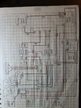
This will probably be impossible to read unless maybe enlarged on a cell phone. Thanks for your consideration... as alwaysView attachment 26990
Attachments
That is a great list of resources.What specific types of information are you looking for?
Victron Wiring Unlimited is the closest thing to an intermediate level comprehensive book that I am aware of. But I have loooots of specific recommendations depending on what you are looking to learn about. Sometimes I feel a bit like the forum librarian
If you look in the resources section of the forum, I have added a lot of the resources that I lean heavily on, FilterGuy Also has some great resources.
I also have a thread where I organize the resources I have found useful, though most of the resources are from much earlier in my learning process
Of note are:
- Victron Wiring Unlimited
- ABYC marine electrical code (this is the most DIY friendly code I have found)
- The Magnum and Samlex Inverter Manuals (I don't own either but I use both documents as references, specifically for grounding related questions)
- The near-comprehensive introductory articles on LFP in my signature from Nordkyn and Marinehowto (and the shorter article by Solacity)
- Videos by Pacific Yacht Systems for general marine electrical design and AltE store solar information at the beginner to intermediate level
- This video on circuit protection as well as this powerpoint
- A great video explaining the basics of electricity on a conceptual level, this video is what made a lot of things finally 'click' for me
- RSD Academy videos and articles on grounding and voltage (among other topics)
- Videos or Articles by Mike Holt on grounding etc, in the context of the NEC
But based on what you are looking to learn I might have other recommendations.
Thanks.
Similar threads
- Replies
- 10
- Views
- 953
- Replies
- 38
- Views
- 948
- Replies
- 33
- Views
- 1K
- Replies
- 19
- Views
- 759