diy solar

diy solar

Electrodacus- can it be this simple?

Aphers

New Member
Joined
Nov 17, 2020
Messages
212
If I wanted to boil it down to the bare minimum, how simple could an Electrodacus-based system be?
E.g. a Victron Battery Protect on the charging side, another one on the load side, and a SBMS0 in the middle?

I know this might not be using the Electrodacus to its full potential, but I'm struggling to get my head around the concept.
Yes.... that would work for a very small system without an inverter. Note: Victron does not support a BP between the battery and an inverter.
 
Yes.... that would work for a very small system without an inverter. Note: Victron does not support a BP between the battery and an inverter.
Thank you, I'm glad that I have a starting point now to build up a system from.
I'm aware of the limitations of the BP, and I know there are other options available (SSR, latching, and N-O relays).
 
I like the chargery but want to point out that for a small system, A FET based BMS like the one @OverkillSolar sells would build a simpler and lower cost system. For a 12 V DC system it is the BMS, 4 cells and some fuses.
Thanks. I was also planning to buy a BMV700 battery monitor, my understanding is that the Electrodacus would provide all of the same information, and more, seeing as it monitors data at cell level. So it may potentially work out cheaper than an Overkill+BMV?
 
The overkill does cell level monitoring. There is no difference there.
The overkill will monitor the state of charge, but it does not have a display. You have to get your phone out to see the data from the Overkill.
The display on the Chargery is a plus..... But I find mounting the display awkward. (From that point of view, I like the Electrodaucus better)
One popular alternative to the BMV700 that I installed in my sisters boat and she is very happy with is the Aili battery monitor. It is a fraction of the cost of the Victron. (A lot of folks on the forum have used it as well. ) Will did a video on the Aili a while back as well.

 
Hmmm. Food for thought. Seeing as I will be using a separate SCC anyway, maybe the Electrodacus isn't the best fit.
Would I be correct to think that either Electrodacus or Overkill can command relays (or other switching devices) on both charge sources and loads. And so the Overkill does the same job but with a 100A FET switch already onboard.

All else being equal, I would definitely prefer a dedicated display for battery charge state. I have a terrible habit of losing my phone...
 
Would I be correct to think that either Electrodacus or Overkill can command relays (or other switching devices) on both charge sources and loads. And so the Overkill does the same job but with a 100A FET switch already onboard.
Yes. That is correct.

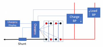
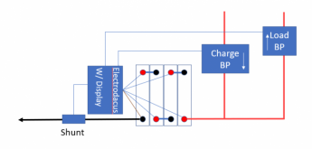
These are three roughly equivalent designs

1618005285046.png
1618005315008.png
1618005352051.png

Admittedly, the Baatery Monitor on the Overkill design has less info than on the Chargery or Electrodacus. However, I find that once I have things up and running, the only bit of information that is regularly needed is the State-of-charge, and the battery monitor will give that.
 
BTW: The overkill is not terribly good for trying to control external SSRs or Relays.
 
I find battery and inverter monitoring and controls via bluetooth and LAN apps way more useful than site displays.

I sit at my kitchen table and monitor and change programing of my SW inverter and Midnite solar charge controller with LAN apps. I almost never mess with the control panels and displays on the devices themselves.
Every situation and person is different on this. I like to be able to glance up and see the SOC without fumbling for my phone..... But I am an old fart that does not use the phone near as much as some of you young'ns do.;)

In a boat or RV where power production can be limited, you are likely to be checking SOC a lot more often. In that case it is very nice to be able to just glance at a screen and know in just one or two seconds what the situation is. In a off grid home that is fully decked out and rarely if ever low on power.... you might go days without checking. In that case, pulling out a phone to check is no big deal. On my grid tied solar, (No battery) I have gone years without checking any data....It just works and I don't worry about it.
 
Every situation and person is different on this. I like to be able to glance up and see the SOC without fumbling for my phone..... But I am an old fart that does not use the phone near as much as some of you young'ns do.;)
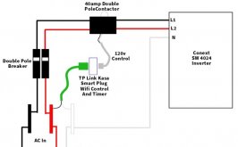
Well there's Ur problem right there. You see, I'm pretty much always on my phone. And the Classic app for the midnite class is but a click away. I'm totalled Decked out for off grid but can be grid coupled too with the click of an app (yeah I have a tp link kasa receptacle connected to a contactor that controls grid ac into the inverter - its even 'Alexa' controlled ) ... But I check my system at least 4 x's A day.

If had to depend on the Schneider Conext SCP display, I'd have to walk out side to the power shed. Ugggg.

(and thanks for the 'young'ns thought. But at my age all that walkin is inconvenient :unsure: ? )
 
BTW: The overkill is not terribly good for trying to control external SSRs or Relays.
Thanks for the diagrams. Why is the Overkill not so good in this respect?

Just for background, this system is for a yacht. I don't plan to use shore power for charging, just solar. All of the loads will be pretty small, well within the capabilities of the Overkill, with the exception of the inverter. I really don't like the idea of running all that current through FETs anyway, and hope to be able to control it by hacking the switch, or failing that an external contactor, possibly on the AC side to lower the current.

On the charging side, my understanding is that there are four possible approaches:
- Get a separate port BMS which can handle the charging current
- Trust the MPPT, and bypass the BMS.
- Get a smart MPPT, and control it via the BMS
- Fit a contactor between the panels and MPPT

That last one seems pretty smart, and the best way to protect both the cells and the MPPT. But the first option is obviously the simplest.

I'll be looking at a charging current of 40A, possibly 60A if I upgrade the panels at a later date.

Have I understood this all ok?
 
Im in a similar situation, setting up a 200ah 4s battery for my Caravan and wanting simple but reliable.

Simple seems to be the overkill BMS and a Aili battery monitor.
Im with filter guy, i want to be able to quickly check SOC and outgoing amps at a quick glance. (With the option of more detailed info through the bluetooth app if needed)
But.... I also want to run a coffee machine that uses roughly 116Amps for about 30sec through a 1500W inverter twice a day. Given all the loses and things I'm guessing I would be pushing the Overkill BMS to its limits.

So maybe the electrodacus is the better option? although would require more components and be more costly.

Im also conscious that the Caravan will be sitting unused for up to 4months between use so not sure how to deal with this in regards to longevity of battery life. Maybe the Electrodacus has better parameters the can be changed to deal with this somehow.
 
Why is the Overkill not so good in this respect?
You can wire up the overkill and use it's output as a signal.... but it is kinda awkward. When you do this, there is only one 'signal' therefore, if the BMS triggers for a under voltage, your chargers are disabled and manual intervention is required. If the BMS shuts off for overvoltage, the loads are disabled and manual intervention is required.

On the charging side, my understanding is that there are four possible approaches:
- Get a separate port BMS which can handle the charging current
Seperate Port BMSs typically have pretty low charging capabilities

- Trust the MPPT, and bypass the BMS.
I have seen will advocate for trusting the MPPT.... but it makes me nervous to have only one line of deffense

- Get a smart MPPT, and control it via the BMS
I am not sure what you mean by this. Are you talking about using a BMS signal or are you talking about some kind of network control?

- Fit a contactor between the panels and MPPT
The coil on the contractor is going to take a fair amount of energy to keep closed.
How would you control the contactor? If you have a signal to control the contactor, then pick an MPPT that can take that signal.


I personally do not like using external contactors or SSRs to control the current.... They just add complexity. (Note: Using an external SSR is no different than using a FET based BMS.... it is just the FETs are in the SSR) Consequently, if the system is small I will use a FET based BMS. However, as the system get to medium or large it becomes difficult to find a BMS that can handle the current. At that point I go with a chargery or electrocutes and pick equipment that I can control with the signals from the BMS.

All of the loads will be pretty small, well within the capabilities of the Overkill, with the exception of the inverter.
What size inverter are we talking about. Anything over about 1400W will be too much for a 120A Overkill.
 
I personally do not like using external contactors or SSRs to control the current.... They just add complexity. (Note: Using an external SSR is no different than using a FET based BMS.... it is just the FETs are in the SSR) Consequently, if the system is small I will use a FET based BMS. However, as the system get to medium or large it becomes difficult to find a BMS that can handle the current. At that point I go with a chargery or electrocutes and pick equipment that I can control with the signals from the BMS.

For larger systems I have helped design using multiple BMSs in parallel to get the current up. I don't like the complexity of multiple BMSs but if there were going to need to be parallel cells anyway, this is a viable option. However in a boat where space is a premium, having two banks of cells can be a problem. (If the system is big enough to need multiple banks of cells anyway.... then it is probably a big system and I would recommend using a Chargery or Electrodaucus and picking inverters and chargers I can control with the signals.)
 
I'd have to walk out side to the power shed. Ugggg.
Like I said.... every situation is different. If the screen is in an inconvenient place.... then the value of 'glancing' at the screen is lost. I would want a way to check on things without walking outside as well.... If there was a reasonable way of doing it, I would still want to have a screen I could glance at if I needed to look at it very often... but pulling out the phone or looking at a computer is more tolerable than walking outside.

Whenever I do a system design, I try to understand the situation and the user of the system. Any design is a set of tradeoffs. What is good in one situation may be horrible for the next. That is why I get uncomfortable when people talk in absolutes about what is the best way to do something.
 
You can wire up the overkill and use it's output as a signal.... but it is kinda awkward. When you do this, there is only one 'signal' therefore, if the BMS triggers for a under voltage, your chargers are disabled and manual intervention is required. If the BMS shuts off for overvoltage, the loads are disabled and manual intervention is required.
OK gotcha. This is not necessarily a deal breaker. The application is a liveaboard sailing boat. I'm unlikely to leave her unattended for more than an afternoon, maybe a couple of days at the absolute max. If I'm off the boat, the only loads on the system are the fridge and freezer. So if I come back to warmer beer than I'd like, I can live with that. The freezer should be well enough insulated to be OK for that sort of period.
I'm assuming that if the charging is cut off and needs manual reset, then my cells should still be protected by the LVD on the fridge, as well as the BMS itself. And if I really expect to be away for a period of time, I would probably empty the fridge/freezer and just shut everything off.


I am not sure what you mean by this. Are you talking about using a BMS signal or are you talking about some kind of network control?
I thought it might be possible for the BMS to tell the MPPT to stop charging. This is all based on the idea that the MPPT can be damaged if it's not connected to a battery. I might be overstating that risk, and there might be better ways of mitigating it, e.g. a dump load from the MPPT? To be honest I'm not even sure that an MPPT exists that works like this, the ones I have looked at cannot be commanded by the BMS.


The coil on the contractor is going to take a fair amount of energy to keep closed.
How would you control the contactor?
I was talking about using the BMS to control the contactor. I'm pretty sure the Electrodacus etc can do this? Again this is all about trying to protect the MPPT, as well as the cells. I figured that a latching relay might be suitable.

If you have a signal to control the contactor, then pick an MPPT that can take that signal.
Is this not what I was thinking of earlier, using the BMS to tell the MPPT to shut off. Or did you mean something else?


I personally do not like using external contactors or SSRs to control the current.... They just add complexity. (Note: Using an external SSR is no different than using a FET based BMS.... it is just the FETs are in the SSR) Consequently, if the system is small I will use a FET based BMS. However, as the system get to medium or large it becomes difficult to find a BMS that can handle the current. At that point I go with a chargery or electrocutes and pick equipment that I can control with the signals from the BMS.


What size inverter are we talking about. Anything over about 1400W will be too much for a 120A Overkill.
Yes I guess it's just moving the problem around. Although I would probably trust the FETs in a BP over a Daly.
I have one large load in mind, the inverter. It needs to be 2000w minimum, and I was going to choose a 3000w model to give me a bit of headroom- hopefully not actually using it at full capacity often, if at all. It would mainly be for cooking, and also the vacuum cleaner and the laser printer, all of which would be operated for short periods and obviously never whilst unattended. I'd turn the inverter off when not using these high current devices- I don't need 24/7 access to AC power.

I had originally considered buying a big-ass Daly but once you're drawing 250A loads, and add a bit of margin, it's no longer all that cheap. And I thought the reliability/lifespan might be questionable. It seemed far better to control the inverter in another way, e.g. hack the switch, use a big SSR on the DC side, or smaller SSR on the AC side to shut the loads off.

And at the risk of sounding like a complete newbie (which I am...) just how quickly do you have to react if something is going awry with the battery? Say the inverter was connected with only its own LVD as protection, and I had some very obvious way of knowing that the BMS had tripped. I could shut it off manually in a few seconds. Is this still too slow to save the cells?
 
Back
Top