diy solar

diy solar

Electrodacus- can it be this simple?

OK.... The moment you start talking about a 3K inverter, it is not a small system any longer.

Here is a design I recently did for a gentleman from Florida that built it and is now exploring the South West in his RV.

1618097043181.png


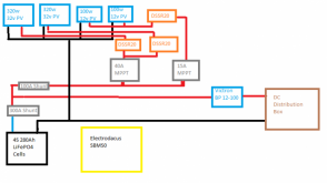
The design is more than you need. Here is a simplified version that is closer to your needs:
1618097721896.png

You would want to tweak it to match your needs. Also, If you don't like the DSSR20 that goes with the Electrodacus SBMS0, you could use a Victron SCC..

I attached a PDF of the two drawings as well.

Finally, if you are putting it on a boat.... don't cheap out on the equipment. Get marine grade or it won't hold up.
 

Attachments

  • sample.pdf
    342.6 KB · Views: 54
BTW: If you decide to go with the Electrodacus SBMS0, this is a resource from @Oberon that you should review:
 
And at the risk of sounding like a complete newbie (which I am...) just how quickly do you have to react if something is going awry with the battery? Say the inverter was connected with only its own LVD as protection, and I had some very obvious way of knowing that the BMS had tripped. I could shut it off manually in a few seconds. Is this still too slow to save the cells?

The truth is that you probably can get away with several seconds....even a few of minutes.... particularly if your LVD is set very conservatively. However, I highly recommend you do not attempt that. Murphy guarantees the one time you walk away for an hour or two is when it will happen.
 
Thank you once again @FilterGuy really useful.
I've already had a good look at Oberon's beginner's guide, certainly demystifies things a lot.

As you say the 3kw inverter changes everything. The other loads are tiny by comparison, maybe 20A max. I would set the LVD to 13v+; it's principally for the induction hob and I have propane as a backup, so I'll only use it when I'm at a high SOC. It is tempting to just ditch it; a 1200w PSW inverter would power the things I can't do without.


Slight tangent, but I'm not 100% sure I understand the way shunts work in these systems. The Overkill I think has a shunt, but if I was bypassing it to power an inverter then would I lose accurate SOC information? And with the SMBS0, do I need to buy shunts separately?
 
The Overkill I think has a shunt, but if I was bypassing it to power an inverter then would I lose accurate SOC information?
Correct. The overkill has a built in shunt for measuring the current. It would mess up the SOC calculation in the overkill if you bypassed it.
And with the SMBS0, do I need to buy shunts separately?
Yes
It is tempting to just ditch it; a 1200w PSW inverter would power the things I can't do without.
Careful.... my experience is that once you have ac plugs you add things you want to power..... A lot of people end up with buyers remorse when they get an inverter that is smaller than they really want.
 
OK don't laugh, this is a work in progress. I've omitted the manual isolators, fuses, and BMS control wiring for now. Am I heading down the right lines with a design like this?
 

Attachments

  • Electrodacus Circuit Diagram.png
    Electrodacus Circuit Diagram.png
    90.6 KB · Views: 24
I would not bother with a MPPT charge controller on the 100 watt panels.
A slight complication that I left out: those 2x100w panels are going to be powering the old lead-acid system when the boat is on passage, and rewired to the main LFP system the other 90% of the time. I'm planning to use a Victron Smart 75/15 to make it nice and easy to change the settings when I make the switch. Having the DSSR20 in there does complicate that a bit of course.

I know that all sounds quite complicated, but boats are generally used in two 'modes' depending on whether you are under way or not. There's a whole set of equipment that only needs power when you're actually sailing, which for a liveaboard is only a very small proportion of the time.
 
I would not bother with a MPPT charge controller on the 100 watt panels.
You loose fault tolerance when eliminating the charge controller. It doesn't have to be a mppt controller, a pwm controller for $15 would work.
 
A slight complication that I left out: those 2x100w panels are going to be powering the old lead-acid system when the boat is on passage, and rewired to the main LFP system the other 90% of the time. I'm planning to use a Victron Smart 75/15 to make it nice and easy to change the settings when I make the switch. Having the DSSR20 in there does complicate that a bit of course.

I know that all sounds quite complicated, but boats are generally used in two 'modes' depending on whether you are under way or not. There's a whole set of equipment that only needs power when you're actually sailing, which for a liveaboard is only a very small proportion of the time.
I run a hybrid LFP-FLA bank. I'm using DSSR20 with diversion to take care of the FLA bank (Through a Bogart SC3020 Solar controller) So when the SMBS0 load/charge is turned off or charged, it diverts solar to the FLA bank
 
You loose fault tolerance when eliminating the charge controller. It doesn't have to be a mppt controller, a pwm controller for $15 would work.
How many safeguards do you feel you need?
 
OK a possible change to the plan.
The supplier for my 32v solar panels seems to have gone AWOL, not answering emails or phone. I may have to try getting my money back and look elsewhere.
This raises the possibility of going 12v throughout. There are pros and cons to this. The panels will be individually smaller and easier to handle, and there will be more shade tolerance. But overall they will cost and weigh more.

Would this then allow me to go without the MPPT? I'll need to read more about this option, surely without MPPT you won't harvest as much energy from the panels? But going without the MPPT cancels out the extra cost of the multiple small 12v panels.
 
OK don't laugh, this is a work in progress. I've omitted the manual isolators, fuses, and BMS control wiring for now. Am I heading down the right lines with a design like this?
I am confused (but I guess that is my normal state ?). Why do you have both MPPTs and DSSR20s?

1618246437759.png

The DSSR20s are the solar charge controllers for the Electrodacus way of doing things (Matching panels to the battery).
The MPPT is a more conventional SCC.
 
The DSSR20s are the solar charge controllers for the Electrodacus way of doing things (Matching panels to the battery).
The MPPT is a more conventional SCC.
The DSSR20s can be use just as a solar disconnect. We now have a fault tolerant system. The pwm charge controller limits max voltage to a (upper) safe level and the DSSR20 disconnects panel to CC at a lower voltage level.
 
I am confused (but I guess that is my normal state ?). Why do you have both MPPTs and DSSR20s?

View attachment 44807

The DSSR20s are the solar charge controllers for the Electrodacus way of doing things (Matching panels to the battery).
The MPPT is a more conventional SCC.

I thought that if using 32v panels I would need to use MPPT to match the voltage to my 12v system?
 
I thought that if using 32v panels I would need to use MPPT to match the voltage to my 12v system?
OK.... then you don't need the DSSR20 unless there is no external on/off controll of the MPPT. What model MPPT is it?
 
The DSSR20s can be use just as a solar disconnect. We now have a fault tolerant system. The pwm charge controller limits max voltage to a (upper) safe level and the DSSR20 disconnects panel to CC at a lower voltage level.

Why do you need the bolded? The CC will shut down if input PV is less than Vbatt+5V in the case of a Victron; and no point I can see to do so at a different voltage point?
 
OK.... then you don't need the DSSR20 unless there is no external on/off controll of the MPPT. What model MPPT is it?

Yet to be chosen. And everything is up in the air now that my solar panels might have to be reordered.
I would probably be using an Epever though, they seem very good value. I think it might only be certain models of Victron which can be directly controlled by the SBMS0?
 
The DSSR20s can be use just as a solar disconnect. We now have a fault tolerant system. The pwm charge controller limits max voltage to a (upper) safe level and the DSSR20 disconnects panel to CC at a lower voltage level.

OK.... I guess that makes sense, but if you follow Dacian the design of the electrodacus system is reasonably fail safe. The predominent failure modes of all of the component are to fail off. Ass an example, the DSSR20 failur mode is to fail OPEN (no current can get through).

Furthermore, if you just use the SBMS0 to turn the MPPT on and off, you already have two levels of protection.
 
I would probably be using an Epever though, they seem very good value.
I have not used Epever so I do not know if it can be controlled with an external signal.

When I design a system with the SBMS0, the decision to use the SBMS0 pretty much comes with a decision to also buy controllers I can control with the SBMS0. If I decide to use the DSSR20, it comes with a decision to use panels that goes with the design philosophy of the DSSR20.

I guess using the DSSR20 in front of the MPPT can work, but it feels kinda awkward to me to have the extra components. That does not make it wrong.... just not the approach I would take. The great thing about this forum is that we get to see what other people do and pick and choose what makes sense for our personal value sets.
 
Back
Top