diy solar

diy solar

Does the BMS have to be connected to the inverter?

Gulam i will be using the Solis in the same way DrPhil is, with the Lead acid setting and custom voltages. My BMS will be seperate and operate to protect the battery if any problem with individual cells or faults etc. I will have no connection between BMS and inverter.

How is the phocos for you? What BMS have you used with it? What comms did you use to communicate between the 2?
Firstly I think you shouldn’t do it, use the solis(my opinion only. Secondly, the Phocos is working really well I have no issues with it. So far so good now running 12weeks.
 
Firstly I think you shouldn’t do it, use the solis(my opinion only. Secondly, the Phocos is working really well I have no issues with it. So far so good now running 12weeks.
The bms was a Daly 100a no coms port, but you use the user defined settings and input into the inverter. So far so good, I’ve been monitoring it, no issues so far.
 
Gulam i have a small setup already with this method, charger is set with custom parameters, inverter cuts out at battery low voltage. Simple setup!

The solis is a nicely specced unit in the UK, 6kw output, 5kw solar, 100amp charging current. Hard to beat and the price is pretty good as well.
 
Gulam i have a small setup already with this method, charger is set with custom parameters, inverter cuts out at battery low voltage. Simple setup!

The solis is a nicely specced unit in the UK, 6kw output, 5kw solar, 100amp charging current. Hard to beat and the price is pretty good as well.
I remember when solis came out, all other brands where put on hold, there was a hard push for sales then.
anyway it’s up to you. By the way you should change the amps charging current to a third of the battery rating. If you have night time tarrif even better charge straight off the mains by pass the inverter as you’ll run it down. More efficient off the mains
 
Our "Peak Rate" time of use her in Los Angeles County, CA USA, is from 4 pm to 9 pm. This time of year, my solar is putting out enough to keep running all of my normal house loads to about 5:30 pm, so I only need to run off my battery bank from 5:30 to 9 pm. After that, I have it drop back to only run the loads in my backup panel, and it can do that all the way to 2 am the next morning. I am only buying power from the utility from 2 am to 8 am. I am still at a credit of a few dollars for the last 3 months. But we do have hotter weather coming, so I need to start running my central A/C more and that will take more power than my solar is producing. Even with charging my battery bank when the sun is up, I am still exporting enough to the grid, that it has been coving the power I am buying back over night.

I have now had the battery bank up and running for over 9 months. Using only voltage control in the inverter/charger and no BMS communication is working great with Li NMC cells. The voltage is actually pretty linear with state of charge, but I knw it would certainly not work this nice with LFP cells. The flat discharge curve on LFP can cause big state of charge errors without a good coulomb counting BMS reporting to the inverter/charger.

My current battery bank is 360 amps hours of 14S Li NMC which works out to about 18.4 KWH. But I do not charge over 90% or run below 20% so my maximum usable is 70% of that, or about 12.5 KWH. But when the grid is up, I actually only run down to about 50% incase I do have a grid failure over night. I need enough power to not only run the house, but to form a solid stable grid long enough for my AC coupled solar to come online to start charging it back up again. I just acquired another set of cells, and I am debating if I want to add 50% more capacity (total 27.5 KWH), and have a spare bank I can use for "portable" power (even 180 AH is pretty heavy), or go all out and double my battery bank (total 36.8 KWH).

With LFP cells, I can certainly see a problem trying to run the way I am. I was thinking my next battery bank may be LFP, but I will have to see where the tech goes over the next 7 to 10 years before I need new batteries with the extra cells.
 
Did you get the extra panels on garage roof yet?

I think you're planning for some DC coupled PV, which would bring the system back if it shut down for low battery. But you still need enough production to supply any connected loads during the time you want to get power from GT PV. How about a load-shed relay, isolating some loads but keeping GT inverters, at some low SoC?
 
No, I have not gotten the extra panels for the garage roof yet. As good as the prices are at San Tan Solar, their shipping is not cheap. That kind of throws the economics off a bit. But they do allow pickup in Gilbert, AZ. I do get sent to work in the greater Phoenix area from time to time, so I was hoping to be able to just pick up a few panels next time I am out that way. But I am not so sure I can fit he stack of panels in my Ford C-Max. I need to take a more accurate measure to see if the 60 cell ones will fit, I know the 72 cell ones won't. I could take my girlfriends CRV, but I would burn about twice the gas on a 1,000 mile round trip.
 
Our "Peak Rate" time of use her in Los Angeles County, CA USA, is from 4 pm to 9 pm. This time of year, my solar is putting out enough to keep running all of my normal house loads to about 5:30 pm, so I only need to run off my battery bank from 5:30 to 9 pm. After that, I have it drop back to only run the loads in my backup panel, and it can do that all the way to 2 am the next morning. I am only buying power from the utility from 2 am to 8 am. I am still at a credit of a few dollars for the last 3 months. But we do have hotter weather coming, so I need to start running my central A/C more and that will take more power than my solar is producing. Even with charging my battery bank when the sun is up, I am still exporting enough to the grid, that it has been coving the power I am buying back over night.

I have now had the battery bank up and running for over 9 months. Using only voltage control in the inverter/charger and no BMS communication is working great with Li NMC cells. The voltage is actually pretty linear with state of charge, but I knw it would certainly not work this nice with LFP cells. The flat discharge curve on LFP can cause big state of charge errors without a good coulomb counting BMS reporting to the inverter/charger.

My current battery bank is 360 amps hours of 14S Li NMC which works out to about 18.4 KWH. But I do not charge over 90% or run below 20% so my maximum usable is 70% of that, or about 12.5 KWH. But when the grid is up, I actually only run down to about 50% incase I do have a grid failure over night. I need enough power to not only run the house, but to form a solid stable grid long enough for my AC coupled solar to come online to start charging it back up again. I just acquired another set of cells, and I am debating if I want to add 50% more capacity (total 27.5 KWH), and have a spare bank I can use for "portable" power (even 180 AH is pretty heavy), or go all out and double my battery bank (total 36.8 KWH).

With LFP cells, I can certainly see a problem trying to run the way I am. I was thinking my next battery bank may be LFP, but I will have to see where the tech goes over the next 7 to 10 years before I need new batteries with the extra cells.
Sounds like you got all the frills sorted.
2 things I would seriously look at if you had funding are solar air conditioning and definitely increasing the battery bank plus a lithium Iron battery charger connected directly to the grid during off peak charging.
If it’s possible to connect the batteries bms to the inverter would be an added advantage
 
I didn’t see the ac disconnect. If you had a line diagram for all the solar set up would be great to see
 
I remember when solis came out, all other brands where put on hold, there was a hard push for sales then.
anyway it’s up to you. By the way you should change the amps charging current to a third of the battery rating. If you have night time tarrif even better charge straight off the mains by pass the inverter as you’ll run it down. More efficient off the mains
I will have 560ah of battery eventually. Initially just got 280ah. So can easily charge at 100amp either way. I have 5 hours of cheap rate leccy at night which i plan to fully charge the battery every night and then use throughout the day, exporting any spare solar to the grid. This way i should get paid by the grid instead of being charged for it.
 
I will have 560ah of battery eventually. Initially just got 280ah. So can easily charge at 100amp either way. I have 5 hours of cheap rate leccy at night which i plan to fully charge the battery every night and then use throughout the day, exporting any spare solar to the grid. This way i should get paid by the grid instead of being charged for it.
You should ready up about charging batteries lifePo4. There are very good tips on longevity of these batteries. Will done a bit on you tube too. Very good advice there.
 
Sounds like you got all the frills sorted.
2 things I would seriously look at if you had funding are solar air conditioning and definitely increasing the battery bank plus a lithium Iron battery charger connected directly to the grid during off peak charging.
If it’s possible to connect the batteries bms to the inverter would be an added advantage
On most mild summer days, I think two small mini split A/C units might do the trick, and only have my big central A/C kick on when it is stupid hot. We typically get about a week of days where it stays over 110F (43C). Even my big A/C just can't keep up. The fun of living on the edge of a desert. My upstairs floor will be fine with just a 12,000 BTU mini, and them maybe an 18,000 BTU for the whole main floor. Mount it high in my vaulted ceiling area, so it takes the hit air up there and cools it off to sink down on us. The return air for my Central air is at the floor in the hall. Pretty dumb design.

Here is my battery summary for 2 days ago.
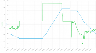
XW-Batt-06-04-21.PNG
From midnight to almost 3 am, my basic house load is pulling 10 amps or so as the battery voltage is ramping down and I have it shut down when the battery drops down to 51 volts. The BMS reported that as 59% state of charge. If the current to keep running my home stays close to that 10 amps, that is about 520 watts for 6.5 more hours. I'll round that to another 3.4 KWHs of energy. We did run the A/C some that day, but since it is back in the main panel, it does not really show up on this graph.

Since I do not have any other charge source besides the XW-Pro going into charge mode for now, I have to manually start it in the morning and it charged at just under 27 amps for 5 hours and 20 minutes. That does work out to about 140 amp hours. 140/360 = almost 40% of the battery bank's 360 amp hour capacity. So that agrees pretty well with the 59% remaining. Technically it is likely more like 50% remaining because the BMS resets to 99% when it stops charging, even though it is only 4.1 volts per cell. That whole charging event fits inside of the extra solar power, so I am still exporting a bit during that time. If (when) I add the DC charging solar panels, the charge current will start much earlier, but ramp up slow, and then ramp back down right with the sun angle. If my calculations are close, I won't need any AC charging. The XW-Pro inverter should be able to stay in grid support mode until there is a power failure. I can adjust the export power to where it uses up most of the solar power.

I am pretty sure the big current spikes around 5 pm and 11 pm are from the microwave oven. I'm not so sure what was pulling high current for 15 minutes straight after 8 pm. I don't think we microwave anything that long. Maybe the furnace fan had to kick on, or the air compressor in the garage.

At 9 pm, I have it stop exporting back to the main panel, so it is just running the backup loads panel again, and just like this morning, it kept running to about 2 am the next morning.

I am still torn on how to integrate the new cells I picked up. I think I might build up my new cells as two separate semi portable 14S 180 amp hour packs. That way, I can take one or both of them if I need remote power somewhere. I want to have a small separate inverter to run from them as well. Each one would be over 9 KWH. I will set them up so each one, or both can be plugged into my XW-Pro system. The only issue will be having to bring them to the same state of charge before I can couple them on. I have a 10 amp adjustable buck converter I can use to push power from the higher pack to the lower pack to get them within a few millivolts. I also have a mains powered 10 amp 14S CC CV charger that I used when setting up my original bank before I had the XW-Pro inverter/charger.

But my main point in this thread is trying to show the huge difference between LFP and NMC cells. If you look back at my battery summary graph, you can see how linear the voltage is while it is under constant current charging. The voltage climbs just a little faster than 1 volt per hour. Going from 51 volts at 50% charge to 57.4 volts at 90% charge in 5 hours and 20 minutes. On an LFP bank, the voltage change from 20% to 80% state of charge difference only 54.8 volts to just 55.6 volts at 80%. The knee just begins above 80 and it might hit 57.6 volts at 90% charged. And all the way down below 20% charged, the knee goes from 54.8 volts down to 51.2 volts at only 4% state of charge.

The one thing I found odd though was the near 0.5 volt drop right before 5 pm. I was wondering what was going on there, but I think I figured it out. While the system was charging, there is some resistance between the XW-Pro and the actual Li NMC cells. So while it is pushing out nearly 27 amps, the voltage inside the XW-Pro was at 57.4 volts, but the cells measured by the BMS are only up to 57 volts even, a 0.4 volt difference. With very little current flowing, the capacitors in the XW-Pro just hang the voltage up there at 57.4 volts. But as soon as the system pulls any real current, like when we kicked on the microwave at just before 5 pm, the cap pulled down, and dropped to the real cell voltage, minus any voltage drop in the system. When the load was removed again, the voltage stayed right at 56.9 volts, and didn't do another big drop like that after the following current spikes. This 0.5 voltage difference between charging and discharging looks like nearly a 50% change in the SOC of an LFP bank. That would be a serious problem. A calibrated battery monitor or BMS that can communicate with the inverter and charger is clearly needed with LFP cells.
 
No cells as yet. The route from China to Ireland was delayed significantly, in part due to the Suez Canal blockage I think.

Latest update is that they should arrive in Poland around June 20th, and then on to Ireland about a week later.

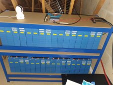
The BMS has arrived from Australia, an assortment of cables, shelving, rods for compression, terminals etc are all sitting patiently waiting.
 
Thanks

I thought that the 5kw inverter had a 3kw limit for battery charge/discharge? The 5kw is the PV input limit.

Again I'm risking revealing my ignorance but I thought that the battery would be charging at 62.5a and the 16s 100a Overkill BMS would be sufficient.

Daly have a 16s 100a BMS also that speaks canbus, but it only comes with a Can to USB cable and the Daly folk were vague about whether it would have a matching protocol.
The Daly does have matching protocol. I have asked them the question. They can’t provide the same protocol.
 
Blast from the past update...

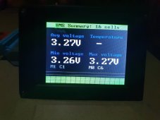
Up and running now using the ZEVA BMS as suggested by @the_colorist

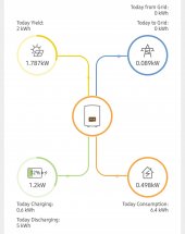
BMS communicating perfectly using the correct protocol. Inverter listing the battery as LG Chem.

20210805_084850.jpg


Screenshot_20210806-103105_SolisCloud.jpg


20210805_085124.jpg

Thanks all for the advice.
 
Great system - a shame the Zeva BMS is no longer made ?
 
Back
Top