diy solar

diy solar

Reverse Polarity RV Plug on Bluetti/Ecoflow/Goalzero?? Is this a problem?

So this video shows the normal 20 amp plugs share a ground. Assuming they also share a ground with the TT-30 plug, then having two RVs/trailers (with bonded ground/neutrals due to their generators) pluged in, would create a short.

If you have ever been camping with RVs, it's really common to have someone run a small generator and have several RVs plugged into it to run some lights and charge batteries for a few hours every night.

 
Update: just realized this is for the ep500pro. They must have sent these to me by mistake because I don't have that model.

Ok get this!! Just got the fusion box and I found a few issues instantly. The ac300 ac200 max have a tt-30, but the fusion box has L14-30 male prong plugs!! They don't connect at all. How bizarre!

Also notice all the mistakes posted on the fusion box sales brochure. The labeling for the plugs is incorrect.

There's also a relay on the 240V outlet plug for one of the hot conductors. I am guessing that it tests to see if everything is connected properly, then it allows you to safely use the plug.

Having the improper plugs confuse me to no end. I hope they didn't make a million of these!

Very nice build quality though. Looks great otherwise.
Hmmmm..... More evidence that these companies do *not* have competency in their product development teams. The question is not "why did they all do it this way? The Question is "How did they all get it wrong?"
 
Update: just realized this is for the ep500pro. They must have sent these to me by mistake because I don't have that model.

Ok get this!! Just got the fusion box and I found a few issues instantly. The ac300 ac200 max have a tt-30, but the fusion box has L14-30 male prong plugs!! They don't connect at all. How bizarre!

Also notice all the mistakes posted on the fusion box sales brochure. The labeling for the plugs is incorrect.

There's also a relay on the 240V outlet plug for one of the hot conductors. I am guessing that it tests to see if everything is connected properly, then it allows you to safely use the plug.

Having the improper plugs confuse me to no end. I hope they didn't make a million of these!

Very nice build quality though. Looks great otherwise.

So that is also wired weird. The circuit board on the bottom with the copper transformer is a switch mode power supply.

The NEMA L14 plug is wired wrong. It should have a neutral and provide 120/240 according to the NEMA standard (and what is printed on the plug). But it does not as there is no common neutral between the two Bluetti. If you follow the red wire, it connects to two points on the L14 plug. So instead of giving two phases of 120v that can be combined into 240v as the plug was designed, you get one phase of 120v, one pase of 0V, and then 240v.

If I am correct, then this can cause issues as people will plug in what fits, and a 240v appliance may also need 120V to work correctly and expect to have 120V at the plug.

I think that relay is there so it can put both Bluetti in parallel and get double the amps at 120v at every plug. With it off, it can do 240V at the L14 plug, but one Bluetti powers half the outlets, and the other powers the other half.

Feel free to correct if I am wrong.

I am not overly impressed that the cable clamp is cracked on the lower black cable.
 
On first glance, it looks impressive. Zip ties, wire labels. It all looks cool, but really look at it. It's very labor labor intensive to assemble. All those wires have to be custom made with correct labels. All the little twist and bends. Wires soldered directly to the PCB.

The PCB should have been made better bringing up the lines to directly, or on top of the plugs and soldered direct, like how they did the 20 amp plugs. Maybe they had the case already designed or reused existing molds and had to make everything fit. Chinese labor is cheap, so they went with using what parts they had and have the labor cost more.

I don't see anything really bad, but meh.

Next to that L14 socket being the wrong socket for the job. That is nasty.
 
Just posted this update:

I've been slammed with emails from viewers on this issue. There are two problems:

1. Specialized radio equipment that has an internal ground to neutral bond, can be destroyed. You will create a direct short through ground if you connect these devices to both the RV plug and the traditional outlets.

2. If you use the RV plug output to supply a panel, and the panel is earth grounded, you can have issues. This could create a safety hazard. You will need to bond it yourself at one point in the system. And bond the hot conductor that you wish to be considered "neutral". If it's a floating system without earth ground, it should be fine actually. But you need to follow ABYC considerations when designing these types of systems.

So overall, not that big of a deal. BUT, they should fix the issue or someone will probably sue them. I am really amazed that such an error would occur by three different companies that have teams of electrical engineers working for them.

Am I missing anything? I have been thinking about it all day and cannot find any other issues that could occur. If you think I am wrong or missing something, please let me know below.
 
As far as I am concerned, if they use any connector, especially the critical one, that has label and has to be connected certain way then they need to follow that, and it looks like they may have poor or wrong assembly instructions, poor QC and test procedures to test the products.
 
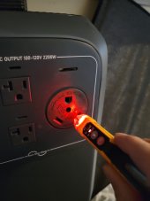
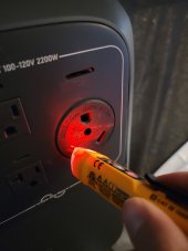
For those of you who think polarity only exists after being bonded, that isn’t true at all. The hot and neutral exist even unbonded. It’s simply difficult to determine with a multi-meter until it’s bonded, because you don’t have the appropriate reference. But with a non-contact voltage sensor you don’t need that ground reference to figure it out. The reversed state still exists (and matters) unbonded with a floating neutral. 1637208701325.jpeg
 
Can you perform the same test on isolation transformer, I.E. 1:1 120V:120V Transformer where the secondary winding is floated (either one of the wire is not bonded to safety ground)?
I thing that BLUETTI may have EMI filter cap connected between one of the pole and ground.
 
For those of you who think polarity only exists after being bonded, that isn’t true at all. The hot and neutral exist even unbonded. It’s simply difficult to determine with a multi-meter until it’s bonded, because you don’t have the appropriate reference. But with a non-contact voltage sensor you don’t need that ground reference to figure it out. The reversed state still exists (and matters) unbonded with a floating neutral. View attachment 72657
What is your "appropriate reference" in a floating system? Aren't they all floating? Why would a non contact voltage sensor determine any form of polarity at all in a floating ac system? Not sure what you mean here.
 
What is your "appropriate reference" in a floating system? Aren't they all floating? Why would a non contact voltage sensor determine any form of polarity at all in a floating ac system? Not sure what you mean here.
The non-contact voltage sensor doesn’t require a ground reference to determine polarity, like simply measuring voltage between pins does. It will only light up on a hot wire. Even in a floating system, only one side is hot.

Even if you bonded the opposite leg to ground, the same pin is still the source of the hot, and the non-contact will quickly and easily show that. The notion that they are both hot/neutral until one is bonded to make that determination is simply silly.
 
Alternating current means there is no polarity. The polarity is constantly alternating. And current does not flow until you have a load and the circuit is complete. Hot has the same potential as the neutral. There is no difference. Same waveform as well.

There technically is no difference between a hot and neutral until you bond one to earth potential. Typically humans are at the same potential as earth, so we call the conductor that has a dangerous potential to be "hot".

In a floating system, both conductors are considered hot. Neither one is tied to earth potential. If it was, then that supply conductor would be considered neutral.
 
If you have Isolation transformer and you have the two wires of the secondary which are floated. Which one of the wire as shown in the right side you think will be hot, which one will be Neutral? I use isolation transformer extensively in the the lab when making measurement in the hot side of the circuit (the device I am testing is plugged into the isolation transformer so I can safely connect my scope to the hot side of SMPS.
 
So with I wonder how this unit compares to all their smaller units? Is this the first one with a 30A plug?

IMO The scalability would lead many people to think this is a great cabin set up hardwired to a distribution/breaker box via that 30a plug. I think some have even stated as such in videos. This entire set up isn’t quite a “mobile unit” one would be tenting where this issue won’t be a problem.

Imagine if the unit had terminal lugs instead of a connector. No one would say this is acceptable.
 
The non-contact voltage sensor doesn’t require a ground reference to determine polarity, like simply measuring voltage between pins does. It will only light up on a hot wire. Even in a floating system, only one side is hot.

Even if you bonded the opposite leg to ground, the same pin is still the source of the hot, and the non-contact will quickly and easily show that. The notion that they are both hot/neutral until one is bonded to make that determination is simply silly.
No, both sides can be considered "hot" in a floating system. Imagine for a second an isolation transformer. There is no difference between the output leads. They alternate and that's it.
 
If you have Isolation transformer and you have the two wires of the secondary which are floated. Which one of the wire as shown in the right side you think will be hot, which one will be Neutral? I use isolation transformer extensively in the the lab when making measurement in the hot side of the circuit (the device I am testing is plugged into the isolation transformer so I can safely connect my scope to the hot side of SMPS.
Exactly! And if you use a non contact voltage sensor, it shouldn't matter what side of the secondary you probe. There is the same potential etc on both wires.
 
Most folks here will know this but I think its worth saying.
The reference for a non-contact voltage sensor is the user's body.
 
For those of you who think polarity only exists after being bonded, that isn’t true at all. The hot and neutral exist even unbonded. It’s simply difficult to determine with a multi-meter until it’s bonded, because you don’t have the appropriate reference. But with a non-contact voltage sensor you don’t need that ground reference to figure it out. The reversed state still exists (and matters) unbonded with a floating neutral. View attachment 72657
20211118_074850.jpg
20211118_074856.jpg
Not sure how you didn't see voltage with your non contact voltage sensor. I did.
 
Alternating current means there is no polarity. The polarity is constantly alternating. And current does not flow until you have a load and the circuit is complete. Hot has the same potential as the neutral. There is no difference. Same waveform as well.

There technically is no difference between a hot and neutral until you bond one to earth potential. Typically humans are at the same potential as earth, so we call the conductor that has a dangerous potential to be "hot".

In a floating system, both conductors are considered hot. Neither one is tied to earth potential. If it was, then that supply conductor would be considered neutral.
Not complete for how the typical split phase power is designed. The neutral comes from the center tap of the transformer and has virtually no voltage potential. The neutral acts like a drain. The hot comes off the end of the coil and has the voltage potential. Yes technically the potential alternates between positive and negative. The hot is very different from the neutral as the hot has the power and voltage potential.

Devices and appliances are designed to cut the hot side to remove power from the internal components and reduce potential faults.

Think of the hot as the faucet and the neutral as the drain. All works great when the faucet has the valve. Putting the valve on the drain is asking for trouble.

This is why plugs and connectors are polarized. Yes the portable generator being isolated reduces the risk. That is great when the generator is outside on the dirt. More potential issues if the generator is mounted and operating in an RV compartment as many do.

These generator with reverse polarity need to be used with due caution or returned as defective. JMHO.

OK so now I see these generators have confirmed a floating neutral in post #80 vs the single hot shown in post #70. These generators do not have polarity and this has long been accepted as OK. Same as the small Honda/Yamaha generator we all have been using for decades. No issue on these generators.

But still Hot and Neutral are not interchangeable in a standard home split phase power system.
 
Last edited:
Back
Top