Inveter 1 is the one that blew the caps, I replaced the board yesterday no errors but the readings are off. The board has several smaller boards that are put into slots. I wonder if those may have an issue but still waiting on the boards from signature and for tech support to call me. I double checked all the panels twice when moving to make sure they were not sharing any panels.Same power from PV1 and PV2, but 2x difference in voltage and current?
Sure you don't have something like 2x string length on on array compared to other ?? ?
Or maybe shading causing similar effect?
(one of three images you posted showed similar voltage, half current and power for one. That could be shading or open string. Got a clamp DC ammeter to check strings?)


You are using an out of date browser. It may not display this or other websites correctly.
You should upgrade or use an alternative browser.
You should upgrade or use an alternative browser.
Very new to solar but started purchasing items, not sure of the final specs of the whole system.
- Thread starter kromc5
- Start date
Hedges
I See Electromagnetic Fields!
- Joined
- Mar 28, 2020
- Messages
- 20,827
Blowing caps is normally expected for over-voltage.
Surge current is another possibility; some blow up if shorted out while full charged.
#1 is the one which was double voltage of #2 in some of your images. But both are high and almost equal in another.
Have you figured out why they blew? Any chance you have a PV string which is over max Voc?
With multiple strings, one could be too long but voltage is held down while a shorter string is in parallel.
Have you figured out why the two showed equal power, but one was double voltage while the other was double current?
I was told the inverters where over-paneled but they never exceeded 138v going in, but I followed everything I was told to the letter twice now. I'm currently waiting on higher tier tech support to call me to further troubleshooting.Blowing caps is normally expected for over-voltage.
Surge current is another possibility; some blow up if shorted out while full charged.
#1 is the one which was double voltage of #2 in some of your images. But both are high and almost equal in another.
Have you figured out why they blew? Any chance you have a PV string which is over max Voc?
With multiple strings, one could be too long but voltage is held down while a shorter string is in parallel.
Have you figured out why the two showed equal power, but one was double voltage while the other was double current?
Last edited:
MrM1
I'm Here, But I'm Not All There
Yes those numbers are very odd. Is each typed up JPG file one for each inverter?
MrM1
I'm Here, But I'm Not All There
If orientation and shading (or lack of ) is the same on Inverter 1 PV1/PV2 array, and Inverter 2 PV1/PV2 array I would think all the numbers would be very close to the same.
Are all the settings in the inverters SCCs all the same?
Are all the wire distances roughly the same?
Are all the voltages at the combiner box (boxes) on the PV in coming sides the same-ish at each breaker / fuse? ?
Are all the settings in the inverters SCCs all the same?
Are all the wire distances roughly the same?
Are all the voltages at the combiner box (boxes) on the PV in coming sides the same-ish at each breaker / fuse? ?
They are all the same in every aspect, I have replaced the pv input and the control board and found the issue remains. Took tons of pictures on the inside of the inverter/wiring and sending to signature. On the 4th call when someone finally picked the phone I was immediately hung onIf orientation and shading (or lack of ) is the same on Inverter 1 PV1/PV2 array, and Inverter 2 PV1/PV2 array I would think all the numbers would be very close to the same.
Are all the settings in the inverters SCCs all the same?
Are all the wire distances roughly the same?
Are all the voltages at the combiner box (boxes) on the PV in coming sides the same-ish at each breaker / fuse? ?

Last edited:
MrM1
I'm Here, But I'm Not All There
Hmmmm ... not inspiring news.On the 4th call when someone finally picked the phone I was immediately hung on
I finally got through and left another message and the person was going to take it directly management.Hmmmm ... not inspiring news.
Last edited:
Hedges
I See Electromagnetic Fields!
- Joined
- Mar 28, 2020
- Messages
- 20,827
Given the way MPPT algorithms can get tricked by a power/voltage curve with two local maxima (two humps), one MPPT at twice voltage and another at twice current are both possibilities if each has a partially shaded 2s2p array. Passing through different shading conditions before reach the same condition of one panel shaded could do that.
Luckly nothing is shaded for all the panelsGiven the way MPPT algorithms can get tricked by a power/voltage curve with two local maxima (two humps), one MPPT at twice voltage and another at twice current are both possibilities if each has a partially shaded 2s2p array. Passing through different shading conditions before reach the same condition of one panel shaded could do that.
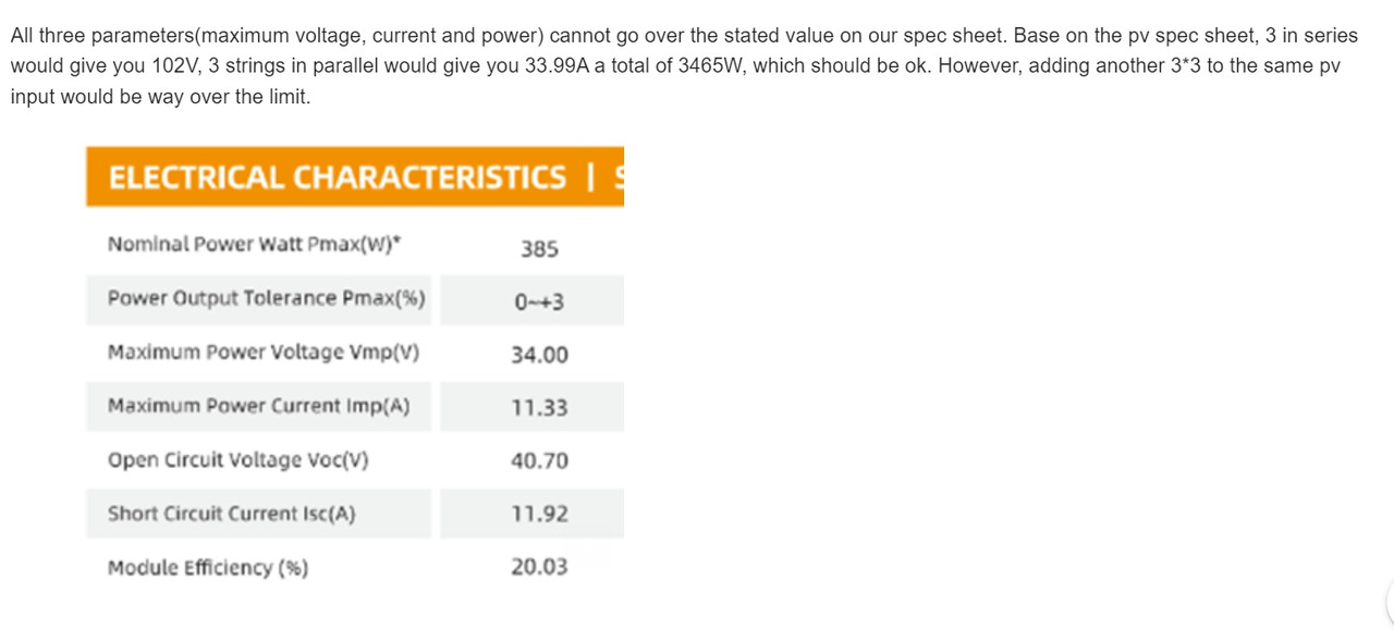
Growatt responded which is very fustrating as I'm way oversold on panels. I told 2 strings of 3 two weeks ago, last week 4 strings of three. Growatt is saying I can only hookup 3 panels by 3 strings per input.
 postimg.cc
screenshot 669 — Postimages
Last edited:
Update signature does not want me connecting my panels to either inverter and wants me to disconnect them. The solution was to use two more charge controllers.
Update for anyone thinking of buying growatt I would advise not buying the 150v models. We have found out it cannot run on 92v but being told not to run it on 138v. At this point I do not know what voltage it could run on mabye the area is the 120v? You have a narrow window it seems for them to function properly. The 250v I was told will run on the 138v so that will be interesting to see how well they perform.
Update for anyone thinking of buying growatt I would advise not buying the 150v models. We have found out it cannot run on 92v but being told not to run it on 138v. At this point I do not know what voltage it could run on mabye the area is the 120v? You have a narrow window it seems for them to function properly. The 250v I was told will run on the 138v so that will be interesting to see how well they perform.
Last edited:
MrM1
I'm Here, But I'm Not All There
You have the 150v dc models correct? But when you replaced the boards, they sent you 250vdc boards? Did you replace the boards in each inverter? Did you confirm with the new boards that you indeed now have 250vdc solar charge controllers?
Per growatt the boards are designed for the 150v model. But the inverter is still not functioning properly with the 54v sitting on pv2 with no panels connected. I took bunches of pictures to show the wiring is correct. But the call ended quickly and I do not have a resolution for it. Since its not functioning properly I would like to correct it even if there is no pv input on it.You have the 150v dc models correct? But when you replaced the boards, they sent you 250vdc boards? Did you replace the boards in each inverter? Did you confirm with the new boards that you indeed now have 250vdc solar charge controllers?
Last edited:
MrM1
I'm Here, But I'm Not All There
Yeah seems like like there might be some other issues there
Signature gave me a huge discount on the sccs but I will need to shut everything down and make room for it all. To fix the other panel issues I was thinking of trying this: going to buy 150ft of this wire and try and use it to pull the cable back through the condiut with the additional 4awg wires needed. It would make a mess but need to dump some lubricant down both sides of the conduit. But I'm not sure if this would work or just dig another trench.
MrM1
I'm Here, But I'm Not All There
Since they are offering you substantial discounts on SCCs, are they thinking there is an issue / defect in your built in SCCs in the Inverters? I wonder why your Growatt 12k Inventer/SCC All in Ones are not being replaced under warranty if they think the built in SCCs are defective.
They do not want me running the inveters at 138v, based on growatt's reponse it failed due to many panels not voltage. Per the solar assistant data the highest I have seen due to cold was right at 140v. The second inveter is still up and running I have per growatts recommendations is 3 string 3p. The question is will it fail or continue to run fine? I plan to take that one offline and remove the pv off it but looking around I'm not sure where to mount them. I had not planned on 6 sccs I may have to mount them over the inveters. There is just to much to move on the bottom to fit them in.Since they are offering you substantial discounts on SCCs, are they thinking there is an issue / defect in your built in SCCs in the Inverters? I wonder why your Growatt 12k Inventer/SCC All in Ones are not being replaced under warranty if they think the built in SCCs are defective.
MrM1
I'm Here, But I'm Not All There
If the prices are not really really good, you might want to look at Midnite solars gear. I love the Classic
The 125ft row is turning out to be a big problem. 3 rows of 5 panels that are at 200v, 3 rows of 4 at 180. Only way to bring those under spec its to add 8 more 4wg lines but that will not fit the conduit. I could take a little voltage drop but even at 6awg I believe it would not fit. I will also need to buy a 7th scc to use for the mounted ones that are left over on that row. Then buy an 8th/9th scc for the ones not finished which I will probally not complete at this time.
Similar threads
- Replies
- 52
- Views
- 4K
- Replies
- 0
- Views
- 372