diy solar

diy solar

Hankzor JK BMS with screen and power button

That's what I use - 16mm² lugs.
I agree, it is an odd choice. @Nami :)
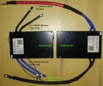
Maybe we will consider improving this problem. At present, all BMS cable specifications are 7awg, but customers can replace the cable by themselves. For 7awg cable, we can pass the current of 200A in the laboratory
 
Maybe we will consider improving this problem. At present, all BMS cable specifications are 7awg, but customers can replace the cable by themselves. For 7awg cable, we can pass the current of 200A in the laboratory
I just received one of these units with two 7 AWG cables. Technically two 7AWG cables would be rated together to handle around 100Amps. I am sure 200 Amps will work, but did you measure the temperature at 200Amps, and for how long they handled the 200 Amps? They are very short leads, which will help. Two 4AWG cables would be better for these pre-soldered leads given they are so short.

Is there any issues or concerns or watch outs with soldering another AWG4 lead to the unit which would bump the margin at 200 Amps? I am thinking of soldering a 4AWG lead in between the two 7's, and crimping all three into a 1AWG Lug
 
Clarity, those Silicone Wires are rated higher than normal wire... in fact look at the extremely Fine Strand Wire which explains WHY these can handle the output... it is well within spec. Same applies to Corse Copper Wire for battery cables versus Fine Wire Welding Capable which can carry double... And comparing to Solid Wire (like house wire) does not apply at all. DC uses Skin Effect while AC does not. (old dead horse, not bringing that back to life, too many love to argue nonsense over that).

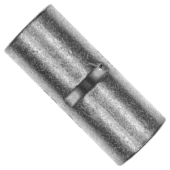
Edit: I am converting my "fleet" to JKBMS. They are all identical with paired 7AWG Silicone Wire for each side. As teh wires are too short for my particular implementation, I connected both 7-AWG together (per side) with a 4-AWG Butt Connector and 4-AWG Silicone Wire as the extension. Hydraulic Crimper used and the connections are perfect, zero issues. NOTE: Not all Butt Connectors will do ! You require a MINIMUM of 10mm, The Linked Butt Connectors below provide for 13mm (1/2") to be inserted on each side with a Dead-Stop in the center to make sure equality on both sides. These also have "grabbers" inside the connector which really locks them in-place. NB: Many Butt Connectors are "short" and few have the grabbers as well. Crimp 4-AWG with 25mm Die.

1653501763349.png
 
Last edited:
May I ask where you were able to get that large gauge silicon cable? Largest I could find so far was 6AWG.
When I ordered the batch of BMS' I also got all the extras, silicone wire, lugs, connectors & interfaces and most other components all at once from my supplier. I sourced the Butt Connectors and the Industrial Shrink Wrap with adhesive more "locally".

EDIT: Just checked, DigiKey also carries it. Alpha Wire & Mueller Industries Silicone Wire can be located.
PS, it's not heavy and can go by AIR to you from China and it is "not" crazy expensive (due to small size & weight). Remember it is not 10kg cells being shipped.

FYI, 7-AWG exists BUT is an Odd Duck... the inclination to just go 8-AWG because it is easy is a MISTAKE, the tolerance is essential and a good solid hard connection is critical.
 
Last edited:
Clarity, those Silicone Wires are rated higher than normal wire... in fact look at the extremely Fine Strand Wire which explains WHY these can handle the output... it is well within spec. Same applies to Corse Copper Wire for battery cables versus Fine Wire Welding Capable which can carry double... And comparing to Solid Wire (like house wire) does not apply at all. DC uses Skin Effect while AC does not. (old dead horse, not bringing that back to life, too many love to argue nonsense over that).

Edit: I am converting my "fleet" to JKBMS. They are all identical with paired 7AWG Silicone Wire for each side. As teh wires are too short for my particular implementation, I connected both 7-AWG together (per side) with a 4-AWG Butt Connector and 4-AWG Silicone Wire as the extension. Hydraulic Crimper used and the connections are perfect, zero issues. NOTE: Not all Butt Connectors will do ! You require a MINIMUM of 10mm, The Linked Butt Connectors below provide for 13mm (1/2") to be inserted on each side with a Dead-Stop in the center to make sure equality on both sides. These also have "grabbers" inside the connector which really locks them in-place. NB: Many Butt Connectors are "short" and few have the grabbers as well. Crimp 4-AWG with 25mm Die.

View attachment 95796
What specification are you referring to regarding the awg 7 amp capacity?
 
I just received one of these units with two 7 AWG cables. Technically two 7AWG cables would be rated together to handle around 100Amps. I am sure 200 Amps will work, but did you measure the temperature at 200Amps, and for how long they handled the 200 Amps? They are very short leads, which will help. Two 4AWG cables would be better for these pre-soldered leads given they are so short.

Is there any issues or concerns or watch outs with soldering another AWG4 lead to the unit which would bump the margin at 200 Amps? I am thinking of soldering a 4AWG lead in between the two 7's, and crimping all three into a 1AWG Lug
If you're experienced with SM soldering, you could go for that. But I feel that your proposed endpoint, "crimping them all into 1-AWG lug" is crazy- bad. Your new and additional wire should end in another lug by itself, with all 3 lugs mounted as a stack on the "-" battery terminal, and all 3 wires ending on a common grounding "-" bus bar. The hole size for your 3rd AWG-4 lug should be either 5/16" (8mm) to match the provided lungs, or maybe 1/4" (6mm), to match the stud on your first battery cell (If the stud size is 6mm).

Although the Ampacity of 7-AWG copper in "chassis wiring" is only 89A (each), these provided leads are silicon-wrapped wire. The comparable figure for silicon-wrapped AWG-7, reaching its full temperature rating (which you absolutely do not want to do), is 312A each. Run at only 100A each of a long period (many minutes), the cords could get somewhat warm - but nothing unreasonable:

With each "side" containing 2 wires of 7-AWG, length about 0.4 feet per side (one "side" consisting of the "P-" pair and the other side consisting of the "B-" pair) the Voltage Drop Calculator "estimated resistance" tab shows .040V voltage consumed. At 200A, VA (watts) is only 8.0 watts (total, along all 4 wires). Some of this heat will be dispersed into the battery terminal (a slightly bad thing), and some will be dispersed into your "P-" bus bar. The rest must be released through the insulation, into free air or conduit.

At maximum continuous output, about 0.31% of the battery power is wasted at the cables in this "heating" process. My high-load situations all involve an Inverter, wasting 20-40x more power within the Inverter. Except for the slight issue of heating the BMS at its terminals, and heating the first battery cell, the advantage in flexibility of the provided cables seems to outweigh the slight disadvantage in "efficiency", in comparison to building my own with thicker wires. I would use 2 "thicker" wires on each of the current terminal pairs, and will not try to add a 3rd wire into either of these sides.
 
2. Are those Micro JST GH 1.25mm 3P, 6P & 7P type connectors? (need to buy crimped cables now)

3. Could you confirm if GPS is a JST ZH 4P 1.5mm? (need a cable for RS485 to USB adapter)
Were these confirmed that that is what they are?

Sounded like I need to connect to the "GPS" port for TTL connection.
 
Last edited:
I connected both 7-AWG together (per side) with a 4-AWG Butt Connector
I just wanted to make sure I understand that you were able to put both of those 7AWG cables into one end of that but connector and crimp that?
 
Yes, I put BOTH 7-AWG into a 4-AWG Butt Connector that has 13mm (1/2") on BOTH Sides for crimping.
LINK HERE: (See the Spec Sheet for proper detail)

Sorry I only have a phBMS Wiring-extensions.jpgoto with it Shrink Wrapped already.
I now have 3 running and there is absolutely no issues whatsoever.
In Fact, after a few "Trials & Tribulations" with the JK Software (What a PITA) and doing the 9V Kick Start I am quite pleased with the results.

Using the enjpower-bms-3.7.4.88 software which WORKS
tHE 极空BMS_4.6.5.apk PROVIDED ONLINE fails to Install. Apparently not quite compatible.

Thank Goodness for @upnorthandpersonal and his diligent help !
Awesome Stuff....

Also an interesting BTW/FYI...
I did the two EV-Cell Packs (the 175's) which were always "cranky" and now they charge, nicely and keep to a tight cell delta from 3.425 down.

I setup Balancing to start @ 3.37V as I am only charging the batteries "Bulk/Absorb" to 3.4375Vpc and Floating at 3.425Vpc so I am never hard pushing above the working range.

Hope it Helps, Good Luck
 
Yes, I put BOTH 7-AWG into a 4-AWG Butt Connector that has 13mm (1/2") on BOTH Sides for crimping.
LINK HERE: (See the Spec Sheet for proper detail)

Sorry I only have a phView attachment 96546oto with it Shrink Wrapped already.
I now have 3 running and there is absolutely no issues whatsoever.
In Fact, after a few "Trials & Tribulations" with the JK Software (What a PITA) and doing the 9V Kick Start I am quite pleased with the results.

Using the enjpower-bms-3.7.4.88 software which WORKS
tHE 极空BMS_4.6.5.apk PROVIDED ONLINE fails to Install. Apparently not quite compatible.

Thank Goodness for @upnorthandpersonal and his diligent help !
Awesome Stuff....

Also an interesting BTW/FYI...
I did the two EV-Cell Packs (the 175's) which were always "cranky" and now they charge, nicely and keep to a tight cell delta from 3.425 down.

I setup Balancing to start @ 3.37V as I am only charging the batteries "Bulk/Absorb" to 3.4375Vpc and Floating at 3.425Vpc so I am never hard pushing above the working range.

Hope it Helps, Good Luck
I have been 'talking' mostly on the other Thread, fairly new (started by Nami on April 22) and incorrectly titled "JK 4S 200A BMS"). Here. The Thread is actually focused on the new models with the heater interface, JK-B1A8S20P-H and JK-B2A8S20P-H. For me, on Android 12, (Pixel 3XL phone) the 4.6.5 software installed with no problem.

This BMS (paper-labeled as the 1A non-heat version) has already arrived for my testing, and I intend to connect to an existing 4s 230 Ah battery pack within a few hours.

I will be using a sledge-hammer crimper to press each provided wire end wire into a decent, thick-copper AWG-6 terminal lug, bolt size 6mm. Following crimping, I will solder into the sleeve of each lug (to fill any remaining gap, even though the sledge crimping should already "fold" the larger copper wire sleeves very tight against the slightly smaller wires). Then I'll use a 6mm bolt using 6mm bolts and nuts (or perhaps a pair of bus bus connectors, if I have any "spares" which can handle AWG 2/0 lying around), to connect each of the paired lugs to a single 2/0 AWG wires for the battery terminal, and the "load" grounding bus - very much as you did.

In addition to the AWG-7 wire size being somewhat small, the actual lugs provided for the BMS end appear to have 8mm holes. A 6mm hole would have provided more contact area, and better strength from the front of each lug to the back. But the provided lugs cover the full width of the BMS terminal pads, and lugs for bigger wire sizes (would probably need to be trimmed to fit that width.

Before adding my lugs on the loose ends, I might cut another in or two from each of the provided wires, to further shorten the AWG-7 wire path segments.
 
I used a "Hammer Crimper" for my 4/0 and some 2/0 stuff, but that is not as "nice" as it should be. So I spent the Big Buck (<$15 USD) and got an 8T Hydraulic Crimper with allows for a double crimp and they are very Tight".

I did look at that thread but last page was was the beginning of Page-2 and have not followed it.
Phunny that NAMI can post & help etc but Chargery's Jason Wang got tossed, as well as others.
I hope those folks remove my name & DIYSolar attribution for any further docs/manuals etc they put out that I had a hand in.

I only pop in Limitedly Now and selective choose how/what I interact with now.
 
Question for those who have gotten JK BMS's from Hankzor. Were they delivered on time or close to it? I have one that tracking tells me should be delivered on 6/18 and that will give me about 3 weeks to get my battery built and installed which should be ok as long as the BMS is on time or not more than a week or two late.
This is my first order from AliExpress, so I have no track record for how accurate their tracking is.
 
I bought my second JK-B2A8S20P, and received it a while back but didn't get around to looking at it much. I mostly expected it would be just like the first one I bought, although I knew the second one was after they were adding the low-temp heating stuff. I didn't want the heater control, and didn't need the display, but other than that, what could change? Now I'm looking at what I got and I'm not sure what everything is.

The first thing I noted was that the RS485 connector is gone. I didn't know I had to specify I wanted it (didn't even know I could), so that was a bit of a nasty surprise.

There was a momentary contact push button (at least I think it is momentary) with four wires to it, and a connector that plugs into the display connector, so I assume this is a ON/OFF for the BMS per previous discoveries by @upnorthandpersonal? Can anyone confirm? @Nami?

The connector on the BMS for the display is of course is a different connector type than the previous JK-B2A8S20P, so I can't use the display I already had with the new BMS. Another annoyance, but minor since I wasn't planning on using the display in the final install anyway.

I also got a connector for what is labeled the heating port (at least that is what Google translate says the label is). Since I didn't order the "-H" version, I didn't expect this.

I haven't hooked it up yet, so nothing really to report. I'm hoping someone here can tell me what the push button is for. I'd assume it is DPST switch and turns the BMS ON or OFF. Anyone know for sure?
 
The button is lighted and press to turn on. Long press to turn off.
 
I just reread this entire thread again and could not find the information on What Version of [B2A24S**P] supports a Power Buttom and/or Screen.
It appears that the "Power Off" button in the APP will not make a reappearance.

I seem to recall @upnorthandpersonal or possibly @Nami posted it somewhere... It is nearly impossible to find considering the number of threads actively discussing different JKBMS things.

There should likely be a Thread that covers "How to Identify your JKBMS and its Capabilities & Functions"

@Nami Could you PM me a picture with the ports of all the current BMS versions out there so we can identify them? I can put them together in a resource and/or the wiki so it becomes easier to keep track of new versions, changes in connectors, etc.
 
Back
Top