diy solar

diy solar

Another Inverter build

Very cool project! I always admire projects like this, I wish I could have afforded to DIY more components of my system.

BMS, Inverter, Chargers take too long (ie too expensive) to develop and build compared to what is commercially available.
I do this in my desire to learn. Also, if it breaks there is a good chance that I can fix it.
For my first inverter build, I designed the power PCB mainly for my R & D, I had to make trace cuts and jumpers just to make it work. Real heat sinks are relatively expensive so, it used regular aluminum angle bars and I was able to gather temperature rise data of the power mosfet groups, the toroid, and the choke. What I learned then is priceless and I am still learning even at my old age.
 
Last edited:
Yes, i understand that - i too wish i was in a financial position to do what you are doing. It is an interesting subject.
 
Update:
Finally finished tracing the circuit of the chinese inverter board I bought. Now, I can troubleshoot and repair in case I damage components during testing.

Sharing my work, not sanity checked so use at your own risk.
 

Attachments

  • 48V to 12V PWM Controller.pdf
    46.6 KB · Views: 25
  • CHIN INVERTER.pdf
    83.1 KB · Views: 22
Typical transformer design is half the loss due to wire resistance and half due to core losses. Not all manufacturers follow this rule of thumb.

Total loss can run from 2% to 10% of rated power depending on physical size and quality of transformer.

You need to estimate the wire winding length to get the total winding loss. Two ways to approach that. Based on gauge, measured resistance /resistance per foot, or approximate average winding layer circumference x number of listed turns x resistance per foot of wire gauge.
 
A final monitor point is heat rise on extended run time to 'find' a 100% duty level - everything kitted together and looking so fine means squat if one is approaching winding sheath insulation limit, and reusing chinesium xfmrs means an unknown variable...
 
Typical transformer design is half the loss due to wire resistance and half due to core losses. Not all manufacturers follow this rule of thumb.

Total loss can run from 2% to 10% of rated power depending on physical size and quality of transformer.

Our needs for an inverter application differ from on-grid use.
Winding losses peak at max current.
Are core losses any more or less depending on load? I haven't measured that.
Off grid we care more about standby power losses.

What I have measured is current waveform. Driving primary and nominal rated voltage, the power transformers I've tested have a distorted waveform. Looks more like a Hershey's Kiss than a Sine Wave. Operating them at half the rated voltage they are much closer to sine wave.
For inverters, maybe twice the wire length, four times the inductance, is the thing to do. e.g. I can use 240 & 240V primary windings as 120/240V auto-transformer.
 
Typical transformer design is half the loss due to wire resistance and half due to core losses. Not all manufacturers follow this rule of thumb.

Total loss can run from 2% to 10% of rated power depending on physical size and quality of transformer.

You need to estimate the wire winding length to get the total winding loss. Two ways to approach that. Based on gauge, measured resistance /resistance per foot, or approximate average winding layer circumference x number of listed turns x resistance per foot of wire gauge.
This is only for the 26V toroid winding driven by the mosfets:
When I was winding it, I used a small piece of wire wrapped once on the "circumference" of where the winding will be. It is 14 inches. So:
Magnet wire length (in inches) = circ. x no of turns + lead length(2) = 14 x 19 +7(2) = 280 inches.
Magnet wire length (in feet ) = 280/12 = 23.33 feet
For awg #14 ohms per 1000 ft = 2.525 ohms or .002525 ohm per ft.
So, for 23.33 ft it is 23.33 x .002525 = .0589 ohm
Since I am using 20 strands, winding resistance = .0589 / 20 = .00294 ohm.

The inverter 24 mosfet H-bridge uses HY4008 with and RDSon = 2.9 mOhms (typ). At any one time 6 hi side and 6 lo side mosfets will be on.
So hi side RDSon = lo side RDSon 2.9 / 6 = 0.483 mOhms
Total RDSon = 0.483 x 2 = 0.967 mohms or .000967 ohm.

Unknown resistances are choke winding, lug connections, circuit breakers, etc.

So, I think the easiest is to complete the assembly and measure battery current at no AC load and at full AC load, then calculate the VAs.
 
A final monitor point is heat rise on extended run time to 'find' a 100% duty level - everything kitted together and looking so fine means squat if one is approaching winding sheath insulation limit, and reusing chinesium xfmrs means an unknown variable...
The toroid transformer I modified to use is made in Canada with tough magnet wire insulation, the added magnet wire I used is Remington brand (USA). I have also embedded a thermistor in the winding to measure temperature. Also, I will not be using the 220v:12V sensing transformer on the chinese pcb.
 
Last edited:
Our needs for an inverter application differ from on-grid use.
Winding losses peak at max current.
Are core losses any more or less depending on load? I haven't measured that.
Off grid we care more about standby power losses.

What I have measured is current waveform. Driving primary and nominal rated voltage, the power transformers I've tested have a distorted waveform. Looks more like a Hershey's Kiss than a Sine Wave. Operating them at half the rated voltage they are much closer to sine wave.
For inverters, maybe twice the wire length, four times the inductance, is the thing to do. e.g. I can use 240 & 240V primary windings as 120/240V auto-transformer.
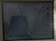
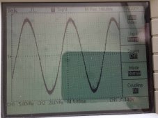
These scope pictures are from the 3KVA inverter I made in 2018 and still running up to now. Half load and overload shows reasonable shaped sine wave. Had to select the capacitor value to match with the choke inductor - toroid transformer to get the shape. The 1.2kw picture is with a malfunctioning IR2010.
 

Attachments

  • Load-1.2kw.jpg
    Load-1.2kw.jpg
    320.7 KB · Views: 4
  • NewIR2010_3.4kw.jpg
    NewIR2010_3.4kw.jpg
    319.7 KB · Views: 4
Last edited:
These scope pictures are from the 3KVA inverter I made in 2018 and still running up to now. Half load and overload shows reasonable shaped sine wave. Had to select the capacitor value to match with the choke inductor - toroid transformer to get the shape. the 1.2kw picture is with a malfunctioning IR2010.

Very nice. Nothing like I see driving a commercial transformer.
Are those traces Amps? (5 "volts" per division)

My measurements were particularly ugly backfeeding a step-down transformer with 120V. Decent forward-feeding 240V winding with 120V


My 9kVA toroids (salvaged from a UPS) are decent


Backfeeding 3-phase step-down was ugly. Forward feeding wasn't so bad, but not what I want for a battery powered system.

They are at the 12vac winding of the toroid transformer.
 
What is the current waveform under no load?
 
What is the current waveform under no load?
You want the current waveform for the 26VAC winding of the toroid transformer? Let me see if I can set it up. Might take a while as I have to insert a shunt, the inverter is outside the house and it is raining right now.
 
Yes, somewhat invasive.
I also use clip-on current transformers, which are OK for moderate frequencies. They don't capture peak inrush. Inexpensive, I recommend for your work.
Then I sprung for a Fluke i2000 "Rogowski coil", which has ranges for higher currents and 20 kHz bandwith. Available cheap enough on eBay.
I've bought a few toys after seeing people at work use them.
I haven't bought the AC/DC hall-effect probes yet. Those are more expensive.
 
The Hall sensors, particularly the servo type Hall sensors are excellent in all respects for measuring both dc and ac.

The biggest advantage is very high noise immunity because the output is completely floating and isolated from a potentially very noisy ground, which is always a major problem with monitoring inverter current waveforms.

If you need higher measuring sensitivity, just loop several turns through the hole.

My favorite is the LA55P, I have salvaged a few of these for free from dead inverters.
https://www.lem.com/sites/default/files/products_datasheets/la_55-p_v18.pdf
DC to 200kHz
50 amps rms ac or 70 amps dc +/- with one pass through the hole.
Excellent zero offset and linearity.

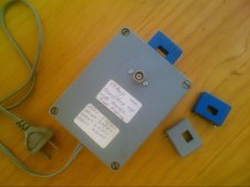
I glued one onto the end of a small plastic box, and fitted +/- 15v dc mains supply inside the box. Output is a coax cable with BNC that plugs into my oscilloscope.
On the 50mV/div range of my oscilloscope, its 1 amp/div
100mV range 2amps/div
200mV range 4amps/div
500mV range 10 amps/div

Had it for years, works like a charm, and its all I have ever needed.
Highly recommended.2023-01-16_0001.jpg
 
Even cheaper from China:
https://www.ebay.com.au/itm/324699634272?hash=item4b999b3a60:g:ORQAAOSwD2Ncn0oK&amdata=enc:AQAHAAAA0BAnUBbnF/YpnYt3sQC/5FUu2m1yNYBb9UzLLEMKzAqhYmUdPOHiFsJ/OXpla3TDwTi7iLiAgaHYHbAl+FpQ60UKcKEdTl+3sFG/EThhz6Gb6V79WwOSzZD6rPcOQ4xQPAfhdvqcFB+7Ov3L2F/41dPGtBuA5lhowvSd841O6vtN9IUdXHlPtxv6NWQC/ZOurvt1R3FyPnlhK65g8cWIwsMSU2ruQ4qTOd8q1Pw5vd7Mv5u+fIJ02BqYMGG+AOUYatHGIUC8p2GF+NiC0Aln6iU=|tkp:Bk9SR7S4nPe2YQ

If you decide to do this, use a transformer supply and three terminal 15v regulators for lowest noise on the dc supplies.
Load the LA55P with a 100 ohm resistor down to ground, and you are in business.
I think you will be very pleased with the result.

*EDIT*
Ah, you beat me to the draw by a minute.
That seller has a very high approval rate too.
 
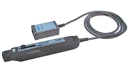
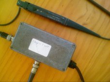
I also have a Tektronix ac current probe P6021 which is now very old. This is a current transformer that goes to 60Mhz and 10 amps rms.
The disadvantage is, that by itself minimum specified frequency is 120Hz, but I cloned the horribly expensive optional Tektronix magic amplifier that goes with it, and allows it to work down to 10Hz.
But I have never used that probe after I built up the LA55P current monitoring box.

For what we do, the LA55P is a much more useful and versatile instrument.2023-01-16_0002.jpg
 
Last edited:
I also have a Tektronix ac current probe P6021 which is now very old. This is a current transformer that goes to 60Mhz and 10 amps rms.
The disadvantage is, that by itself minimum specified frequency is 120Hz, but I cloned the horribly expensive optional Tektronix magic amplifier that goes with it, and allows it to work down to 10Hz.
But I have never used that probe after I built up the LA55P current monitoring box.

For what we do, the LA55P is a much more useful and versatile instrument.View attachment 129801
Wow, that reminds me of when we used something smilar to it to scope the X-Y and Sense/Inhibit lines of magnetic core memories. (shows how old I am. LOL)
 
Back
Top