diy solar

diy solar

Magic Smoke came out......... ##it happens

So, don't leave us hanging. What did the vendor say?
Sent a message thru the Signature Solar support webpage Tuesday. This way I won't have to sit on hold. I have not heard any acknowledgement they have read the message and no response. This is a test of their support, in previous videos I related my experience with tech support and how bad it was so I guess I'll be making another documentary that possibly things have not improved there.

Why have a support webpage with messaging if you don't ever read the messages that come in? Or respond to them?

The joke just continues to play out every time someone needs support. Extremely poor management.
 
Yo, @SignatureSolarJess - you have work to do
Thanks for the tag! How can I help? This email was sent to us May 8th at 10:27am and we responded, May 9th 10:11am.. Our email team aims to respond to each email within a maximum of 24 hours but for a faster response, you can call 9034412090 to speak with a technician. Our wait times are typically around a minute long. In the past they were much longer but we have increased staff and this has improved wait times exponentially :)
 
You spoiled the fun. :ROFLMAO:

I like to test their system and report on it. Next time, I'm not posting about it. :)


That is me... Super spoil sport to the rescue. Spoiling sourpuss who rather be unhappy everywhere. :)
 
That is me... Super spoil sport to the rescue. Spoiling sourpuss who rather be unhappy everywhere. :)
It is test with SS support. How long or bad can they screw up?

One of my most viewed videos was about the failure on their end regarding tech support.

I'm not going to sugarcoat things but I will give credit if it is due. Marcus took care of me when I first installed the charge controllers and there was a F01 code setting. Regular tech support was just horrible. https://diysolarforum.com/threads/e...mppt100-48hv-sets-code-f01.68669/#post-867926

I can't say enough good things about the charge controllers, they have worked flawlessly since the firmware update. These do exactly what the units were designed to do. It is the other half of the equation that was lacking.

I can't give an honest opinion if things don't play out for the average person that buys from there and needs support.


The average person doesn't do DIY, they hire it out. The above average person (or the cheap person) does DIY and is on here to learn about how to do things :)

So you are above average, congratulations, your prize is in the mail. If you don't receive it in 2 centuries write a letter to me care of ice station zebra at the north pole.
 
The average person doesn't do DIY, they hire it out. The above average person (or the cheap person) does DIY and is on here to learn about how to do things :)
They watch videos to learn from others. Some of the subscribers are from here but some are just searching and researching.

Honest experiences matter to me, I turn off promo type videos pretty fast. I do like to see others experience, honesty and different setups with different ideas.
 
Thanks a lot for this video.
After watching it I went and checked the terminals on my inverter and 2 of them were looser than they should be. Definitely they seem to loosen over time. Will have to keep an eye on that. Again thank you.
 
Victron specifically says not to use ferrules (except on screw down terminals). You may cause increased resistance. The terminals for both Victron equipment (besides the connections that are for lugs) and IMO are clamping style terminals
I'm confused. It looks like all the connections in this video are screw down terminals, so didn't he do the right thing by using ferrules? If you use a screwdriver to set the wire, that's a screw down terminal, isn't it?
 
I'm confused. It looks like all the connections in this video are screw down terminals, so didn't he do the right thing by using ferrules? If you use a screwdriver to set the wire, that's a screw down terminal, isn't it?
These appear to all be clamp type connections.
 
Thanks a lot for this video.
After watching it I went and checked the terminals on my inverter and 2 of them were looser than they should be. Definitely they seem to loosen over time. Will have to keep an eye on that. Again thank you.
Cables move under surge loads sometime minute’ movement sometimes noticable. Why there are cable forming and tie downs on big equipment ….. 1600/24 cable moves on locomotives and must be restrained so it doesn’t chaff and short.


OP has a very nice system. Great job. If anything gets loose in a string - run then it can create domino effect… all up down wire with surging. Good job on looking and vigilant inspecting. Most ppl stop looking - inspecting at first repair.

If you’ve ever replaced big welding lead clamps they come with copper foil that wrap around wire before shoving it into clamp to be tightened. The welding leads while big in size have strands…loose strands have caused problems and with your higher voltages more problems are likely. We terminate all wires on locomotives …..burndy clamp type connecter and twist wire nuts were not allowed.
In Aviation we limited the-number of opens - connections for runs of wire. Some wire has to be full run never spliced for repairs in the middle. Every connection adds up and is potential failure point. Locomotives didn’t have potential fall from sky so runs were spliced and everything in between.

IMG_6400.jpeg


Are these your panels? 8x ~50vdc is ~400 working voltage at ~13.72 amps if string is all in series. You are working with dc voltage. You are using 10ga wire for pv over a very long run?. 4kw PV cycles up and down and can = does spike.

Might want to check that.

IMG_6401.jpeg
IMG_6403.jpeg

I used 3% for drop vs 5% because of way pv surges…. This scale is normal 5%. PV is not really constant voltage nor amps which makes it harder to size. They spike in cooler weather. Right?
IMG_6404.jpeg


The ppl that previous owned my home plugged their 120vac 30amp rv plug into a wall outlet with one of those adapters….they went to panel and replaced 15amp breaker with 30 amp breaker on 14ga wire. I had to replace the entire run of that wire heated in every spot. Every connection had been hot. That 14 ga wire carried it but wires were hottest at plug.

Any Heat loosens connection. I hate spring connecters like victron and others - EG4 6000xp are using now. High amps and high voltages make leads move anyway. Like water pressure makes garden hose jump….sometimes noticeable sometimes not. Water hammer is like surge.

Nice system OP.
 
You are using 10ga wire for pv over a very long run?
Wow. @Zwy
Could what @D71 said be related to your problem?
I was originally planning to do 100 yard runs to my panels and was told I would need 8AWG to keep voltage loss to within acceptable levels at that distance, and I'm running lower voltage than you are. Long strings of 8AWG was too expensive I abandoned the idea.
But if you're running 10AWG over long distances at pretty high voltage. Maybe it's causing wire heating issues for you?
It will be most obvious at connections where resistance is higher. Why we ran straight runs and no splices - connections on aircraft - aviation - (edit) other breaker) source to load.

My findings others may differ the pressure breaks weakest link. Why water and electricity are used to describe events…to ppl learning. Drinking out of warm garden hose cooked by sun. The initial water is warm if hose is in direct sun light. Most ppl never drink out of water hose but drink from pex all the time. 😳

When in the Navy I worked on Lockhead ES3-A aircraft. It was originally a submarine hunter that was converted to electronics warfare.

In that plane the generators on the engines feed the main load centers. Those all went through breakers. From the breakers they went to cannon plugs with anywhere from 2 pins to several hundred. That passed it through the bulkhead to another part of the plane. From there it would feed port and starboard electronics bays internal and external. Also external port and starboard bays at the tail. Also wiring up in the tail to run the hydraulic actuators to fold the tail and the radio antenna. In each bay there was a bulkhead connection to the racks. Then cannon plugs to the equipment.

All that said any wire on the plane would pass through anywhere from 4 to 12 connections.

We had 30day, 90day, 120day, 240day inspection cycles. During the 240day we basically disassembled the plane and took everything apart down to the last bolt and screw. Then we put it all back together with clean connection and thin film preservatives on every connection, screw and bolt.

Those airplanes flew from 1972 through 1996.


My point being cleaned and inspected makes it safe so long as it is maintained.

For battery banks it only makes sense to use as few or as many connections as needed to do it right.
I had a&p license stopped working on them went back to college. Returned license to faa. Ppl with helicopters don’t want to do proper maintenance. All chip detectors and fire detection circuit were straight run …. No connecters repairs on helicopters .. many radio nav were same….j600 section all tiny wire straight runs.
Like stated some.

Consistence is my failure i left out specifics in next post.

IMG_6405.jpeg


We also secured every cannon plug with .020 lock wire. Somethings for safety had breakable .020 copper safety wire on other items. Before that there was tye strings as well as spring cammed twist locks that secured with spring tensions for connection.

Amphenol Plug Are common and lockwired in aviation You are correct there are lot connection for some circuits there were also tb about repairs and allowances.

 
I had a&p license stopped working on them went back to college. Returned license to faa. Ppl with helicopters don’t want to do proper maintenance. All chip detectors and fire detection circuit were straight run …. No connecters repairs on helicopters .. many radio nav were same….j600 section all tiny wire straight runs.
Like stated some.

Consistence is my failure i left out specifics in next post.

View attachment 214732


We also secured every cannon plug with .020 lock wire. Somethings for safety had breakable .020 copper safety wire on other items. Before that there was tye strings as well as spring cammed twist locks that secured with spring tensions for connection.

Amphenol Plug Are common and lockwired in aviation You are correct there are lot connection for some circuits there were also tb about repairs and allowances.


I still have my set of safety wire pliers from my kit and still use them from time to time. A lot of the larger ones had a locking feature when turning. But the ones in hard to inspect locations were all safety wired.


Edit: I apparently have 2 sets, just ran across a second set.
 
Last edited:
I still have my set of safety wire pliers from my kit and still use them from time to time. A lot of the larger ones had a locking feature when turning. But the ones in hard to inspect locations were all safety wired.
Some ppl argued the safety wire pliers damaged the lock wire so twisted the required twist per inch by hand used duck bills for last tight twist. :) Young guys put on beautiful lockwire and get mad when I cut it say do over….they put neutral or negative safety wire where it wasn’t allowed. 🤣
 
Some ppl argued the safety wire pliers damaged the lock wire so twisted the required twist per inch by hand used duck bills for last tight twist. :) Young guys put on beautiful lockwire and get mad when I cut it say do over….they put neutral or negative safety wire where it wasn’t allowed. 🤣


When I was doing my CDI thing I would always count the number of twists per inch and the length of the wire folded over. And they were pissed when they had to do it over and we never let the newer guys to that step until they had watched and learned and demonstrated they could do it right.

We had a couple of newbs that for some reason got sent to pull a amplifer tray from the plane. They get out there and there are two little cannon plugs. They don't unscrew like the others but they tried and tried again and when they couldn't get it done rather than getting someone else to look they got a pair of vice grips and twisted some more.

The style plug was one where you pulled the collar back away from the socket to release it.

Two things happened - we ordered new ends for the wire and made the guys that broke it repin them into the new plugs. And we transfered one of them to dayshift and told them they only thing they were ever allowed to do together again was plane washes. Took 6 guys about 3 hours to wash a plane.
 
  • Like
Reactions: D71
Wow. @Zwy
Could what @D71 said be related to your problem?
I was originally planning to do 100 yard runs to my panels and was told I would need 8AWG to keep voltage loss to within acceptable levels at that distance, and I'm running lower voltage than you are. Long strings of 8AWG was too expensive I abandoned the idea.
But if you're running 10AWG over long distances at pretty high voltage. Maybe it's causing wire heating issues for you?
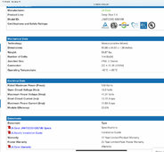
Vmp of my panels 41.84V. Imp is 12.67A. 8S comes to Vmp of 335V.

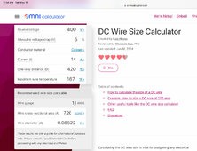
That is at peak sun and at test conditions of 25°C. Inputting the data into the Southwire calculator, the voltage drop is 3.26% from the resistance of the wire. In my video you will see 300V on the display, the panels were in the sun all day and the panel temp was over 25°C so there will be some loss of voltage. Add that with the lower sun angle after 4pm plus the sun will be almost heading behind the array pointed due south as we get closer to summer solstice.

String voltage should be as high as possible with VOC at lowest ambient temp calculated to stay under the VOC rating of the SCC. As I have 16 panels on the array, the 8S configuration makes the most sense.

Voltage drop on PV is just a loss. I would be more concerned about power loss with higher amperage. Running 12.67A at peak sun with as high of a string voltage as possible is the best choice as power loss runs at a factor of I^2R = W. Hedges covers this in this post.

If I was running parallel strings where the amps would double, then I would be concerned with wire heating resulting in power loss. At 12.67A at peak sun, it is not a concern with running 10AWG in a single string.

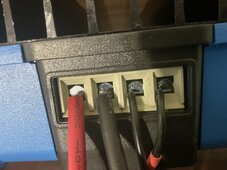
The failure was at the connection point. Each connection will have resistance and that resistance generates heat. The higher resistance could have been on my connection or the manufacturer connection. One thing that will occur when the new SCC comes is I will remove the top cover and check the manufacturer connections. I found some connections in the other SCC that I was able to tighten, every connection I had made was still tight. That doesn't mean I did not miss one at the initial install but I always double check my work. I would have to miss it twice. I don't see the odds of that happening. Another possible factor is the use of the ferrules, I will be removing ferrules on all the clamp type terminals.
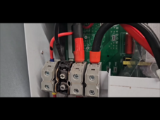
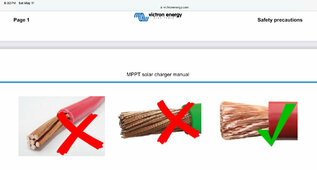
I have noticed that some battery wire has super fine strands. I'm using 2 AWG wire and the super fine strands didn't work very good with the clamp type terminals with or without ferrules. The welding cable sold by Temco isn't so fine and works better in the clamp type terminals without ferrules.
 
I agree… 100% with OP the weakest point was most likely factory connector inside the EG4 solar charge controller. it is where the smokes was greatest
Domino effect. A Video screen shot from his video ….Primary failure was EG4 factory side. Weakest link.

Op stated "ferrule" was his initial post concern.

IMG_6408.png


I’d still look at pv wire gage size for the run. One other thing might be what are the ferrule connectors made out of for the pv connections in EG4 MPPT box where it burned up. Steel for some connectors is not good idea in system I had some old ferrules and noticed they stuck to a magnet. What are these connecters for contacts - surfaces surfaces in EG4 MPPT?
If magnet sticks might not want to use it for ferrules - crimps.

Can you believe Victron wants 6ga wire from Smart Charge Controller to batteries pay attention to wire strand type and insulation wire stick out. They will blame failure on not doing it that way.

I will be using 10ga PV both sides when put it up permanent. This is VICTRON examples for the Smart Solar 150/35 MPPT.
The problem becomes do you do as Manufacturer suggests or not?
IMG_6415.jpeg

I’ve got 16ga wire in there to test it … 🤣 Notice anything for bite and cross section clamping based on design? Notice how the terminal is shaped for forming the clamping action on the round wire. See it. That method of connection provides more contact surface conforms to round wire. For the price hope those shiny connectors are plated quality - metals. 🤣 had hard time getting the 16 ga to bite. 🤣 it is only temporary and was testing it before putting on shelf… had 30 day return window. I test everything when get it now. Nothing worse than buying it … place on shelf then find it doesn’t work later. Return window closed. Stuck.


IMG_6412.jpeg

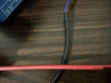
I’ve been using this PV wire…expensive.
  • BougeRV solar cable is certified by TÜV and UL. The dual sheath is made with XLPE insulation, which ensures it can work stable from -40℉ to 194℉, while PVC wire can only handle 158℉ at maximum. BougeRV solar cable wire is UV resistant, which makes the cable much better for running in outdoor solar arrays.
  • WATERPROOF AND DURABLE: An IP67 waterproof ring on the male solar connector is perfect for sealing out water and dust to prevent corrosion. The connector is stable and safe with the built-in lock, which is durable outdoors. The PV cable is designed to withstand extreme heat and cold.
  • 1000vac 1500vdc
IMG_6413.jpeg
Again OP has very nice … Install - nice system.

I however think the high voltage pv ~500v is still growing…. I’ve read it may go a lot higher for PV - inverters mppt in the future..
 

Attachments

  • IMG_6415.jpeg
    IMG_6415.jpeg
    149.8 KB · Views: 1

diy solar

diy solar
Back
Top