EG4 LifePower4 batteries actually have two RS485 (modbus) serial busses (as well as a CAN bus).
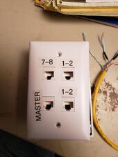
Pins 1 and 2 (orange/white and orange, normal ethernet) form one bus.
Pins 7 & 8 (brown/white and brown, normal ethernet) form the second bus.
If using the EG4 Communications hub:
The hub polls the batteries on pins 7 and 8. Any other communications on these pins such as to SA will generally fail due to traffic congestion on the bus. SA will work fine if you use pins 1 and 2.
If using one EG4 Battery set to Address 0 (all dip switches down):
This places the BMS in host (or master) mode. The BMS polls the other batteries on pins 7 and 8. Any other communications on these pins such as to SA or the inverter will generally fail due to traffic congestion on the bus. SA and/or the inverter will work fine if you use pins 1 and 2. The inverter must support the EG4 BMS (Narada) communications protocol. SA does support this protocol, SunGoldPower does not.
The SGP 10K Inverter BMS RJ45 connector uses pins 7 & 8.
The SGP 10kw Inverter Wifi RJ45 connector uses pins 7 & 8. Pins 1 & 2 are 5vdc power for the Wifi dongle. SA can read the inverter status from this RJ45 jack. It is what I use as the USB to RS485 converter provides some isolation.
I have six batteries in a rack. Battery addresses are 1 thru 6.
I am using an EG4 communications hub between the battery stack and a SunGoldPower 10kw inverter as the inverter does not support the BMS (Narada) communications protocol.communications protocol.
Most inverters want to see 0x46 as the device code in the communication data and EG4 uses 0x4A. There are several other differences in the data as well. The hub solves these issues.
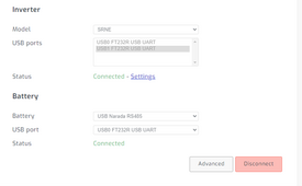
I have the Wifi RJ45 port on the inverter pins 7 and 8 (ensure pins 1 and 2 are cut/not connected as they have 5vdc and ground for the dongle power) into an USB to RS485 converter plugged into one SA usb port.
I have one RJ45 port on the bottom battery in the stack using pins 1 and 2 into an USB to RS485 converter plugged into one SA usb port.
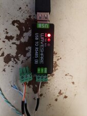
I use two USB to RS485 converters. I have cat5 cables (pre-made commercial) in which I have cut off the RJ45 connector on one end, stripped back the insulation and connected the required two wires (orange/white and orange or brown/white and brown). I use short USB cables from the converters to SA for my use as the SA ports are to close for two converters as I use one USB port for a 10 inch touch screen display.
SA shows all six batteries and also shows all inverter stats including the SOC as reported by the hud to the inverter.
The hub also lets the inverter know what the bulk charge voltage is and this is settable on the hub as "Max Charge Voltage". The "Max Charge Current" can also be set at the hub.
Updated the EG4 LifePower4 battery firmware from 3.10 to 3.32
The baud rate on pins 7 & 8 changed to 19200 while the baud rate on pins 1 & 2 remained at 9600
I updated the EG4 Communications Hub from 1.8 to 1.10. Since the hub talks to the BMS on pins 7 & 8 the baud rate of the hub needs to be updated to 19200 as well. If I update the baud rate on the hub with the 1.8 firmware (I have two hubs) to 19200 it will also communicate with the batteries.
Likewise depending on which two wires you are using the BMS_Test software baud rate also needs to be adjusted accordingly.
This link is to a spreadsheet with the parameter settings for the EG4 Lifepower4 batteries. Addresses 1 thur 5 have firmware 3.32 and Address 6 has firmware 3.10
BMS Version Comparision