diy solar

diy solar

New no battery pure sine wave solar power system with smart switchers.

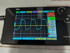
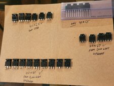
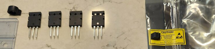
Interesting response: Testing new P & N MOSFETs Gate open/Gate close test at 100k resistance at just 9VDC.

No problems operating the gates, at no matter opening or closing the gate.

Only the P FET demonstrated a micro time delay on closing, Suggesting my 15K gate close resistors are wrong and a much better value is 40K on both FETs.

Good news is they both will respond the same to lower test voltages.❤️

Back to the bench to swap out the gate close resistors to 40K, will be ready for full testing tomorrow.

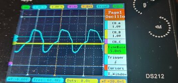
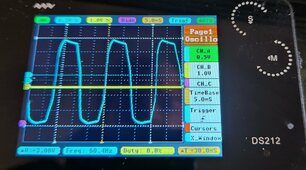
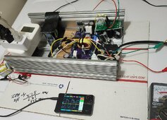
WOW before and after photos, was over driving the gates in both directions, Much better sine wave and power curve.
P FET is the top on the scope N channel on the bottom .
Can't wait to test.

More soon 😀
 

Attachments

  • 20240606_210734~2.jpg
    20240606_210734~2.jpg
    291.9 KB · Views: 1
  • 20240607_171228~2.jpg
    20240607_171228~2.jpg
    315.8 KB · Views: 1
Last edited:
Huge steps forward with 40K gate close resistors and lower driver input signal to the optic couplers.

Bulb glowing noticeably brighter at dual 24VDC bench test voltage, Suggesting 140VDC may ultimately be the correct dual input voltage for the two FET inverter, will continue 160VDC testing hoping to push big loads at higher output voltage.

Just to let you know first test with 40K gate close resistor, Found spikes on both halves of the sinewave, reducing the optic coupler drivers more produced the wave in this picture. Normally the top P channel is rounded and the N channel is a bit squared. If this wave form holds up with higher voltage my ISO transformer through put issues may be solved. N channel is the best so far.

See pictures in previous post, Solar testing tomorrow 💚
 

Attachments

  • 20240607_171228~2.jpg
    20240607_171228~2.jpg
    315.8 KB · Views: 1
Last edited:
A new day 7:25 AM system has been running since 3AM and is lighting up as the sun rises, no additional loads till full sun 9AM and beyond.

8AM big sun just hit the panels 141VAC and the bulbs are burning really bright, all is still running smoothly.
If the system had a voltage controlled relay it would be adding in additional loads. Waiting for 9AM +

8:30AM still maintaining 140VAC output from the two FET inverter, So far perfect blue sky day 💙

System is double glass fused at 5amps so I can only push it just so much, the red LED indicator light on big heater has stopped working days ago.

More here in about in about an hour and a half❤️
 

Attachments

  • 20240608_071511~2.jpg
    20240608_071511~2.jpg
    192.9 KB · Views: 2
  • 20240608_071427~2.jpg
    20240608_071427~2.jpg
    87.2 KB · Views: 1
  • 20240608_071419~2.jpg
    20240608_071419~2.jpg
    168.2 KB · Views: 1
  • 20240608_071411~2.jpg
    20240608_071411~2.jpg
    187 KB · Views: 2
  • 20240608_071606~2.jpg
    20240608_071606~2.jpg
    203.9 KB · Views: 2
Last edited:
9:15 AM mixed results from dual 160VDC input testing, Pictures are from 225 watt small heater and the two lights test, Maintaining 122VAC❤️

After the pictures I turned off the small heater and turned on the 500 watt first stage of the big heater ran fine for a couple minutes than I noticed the output voltage was down to 100VAC and attempted to boost it up just a bit with the optocoupler adjustments, as with previous testing the voltage increased slightly and then dropped off suddenly last thing I saw was 96VAC and both FETs shorted source to drain.

Conclusions: 160VDC provides higher output voltage but not necessarily more watts/amps output, Actually pushing slightly more watts 550watts at 140VDC than 160VDC, Will update all parts list and zip files.

Not sure where to go next the output of the P channel was getting squared as the load increases (I have seen in the past better wave form from the P FET, N channel is rounded and beautiful) suggesting more adjustment on the P channel.

Changes that worked 40K gate close resistors, 12K 5 watt for the two 12VDC floating power supplies, Fixed resistors once you determine optimum settings.

Avoid any spikes on the scope, Avoid moving the adjustment higher when under load, Avoid pushing the system voltage below 100VAC.

More later going to enjoy this beautiful day 🌞
 

Attachments

  • 20240608_085123~2.jpg
    20240608_085123~2.jpg
    90.6 KB · Views: 3
  • 20240608_085133~2.jpg
    20240608_085133~2.jpg
    155.2 KB · Views: 3
  • 20240608_071411~2.jpg
    20240608_071411~2.jpg
    187 KB · Views: 3
Last edited:
Ordered more 555 timers and P FETs, Enough to build out the remaining V1.2 purple boards.

More testing/adjustments needed getting the P channel back to a better sine on the top wave is a priority (Thinking 25K to 30K gate close resistor for the P channel will fix it, the 40K on the N channel is absolutely beautiful)

Looking for more amperage but in case you are still interested right now the two FET inverter will push around 500 watts of electronics and lighting just fine, It is only when I start pushing the adjustments higher that things go wrong. Hate damaging parts but I learn something every time, better it happens to me rather than you.

The quality and stability of the inverter is steadily increasing😀

Getting close to putting the new two FET to work full time, only regret from this morning is not letting the big heater run longer and get a picture of the red glow, the voltage was 100VAC and if I had just left it alone it would have likely run the heat and lights all day.

Also have not tested multiple two FET power boards on the same set of solar panels to get more watts/amps output.

Stick around not done with the improvements yet, A few bumps in the road but also making real progress.

While I am waiting on the parts think I will build a voltage controlled relay just for the two FET inverter, Proven today if you disconnect the main loads when the voltage hits 100VAC and reconnect at 120 +VAC you can run the 60Hz signal 24/7 or timer controlled sun up hours.

Like the higher voltage availability with 160VDC input but evidence is piling up that 140VDC dual input is the correct input voltage.

More later
 
Last edited:
I have about a dozen good 40N65 MOSFETs to back up the new two FET inverter, down to the last P Mosfet until new parts arrive.

My advice during bench testing at the dual 21-25 VDC level, only power one channel at a time and looking at your oscilloscope and the inverter main output, starting at the lowest setting on the 50K potentiometers slowly bring up till the FET starts and produces upper/lower humps (run scope at 5.0ms-10.0ms)
Adjustment for the best upper or lower sine half wave.
Next test both at the same time for full sinewave, reduce any spikes to best sinewave possible. Carefully disconnect each potentiometer and read the resistance with a digital ohm meter, replace each 50K potentiometer with fixed resistor, You can do a similar thing with the 60Hz timer mine uses a 51K resistor and runs at 60.4Hz😀

If you do this correctly you will avoid the the mistake I have made the past four times of testing full solar. Simply put turning up the optic drive too high causing phase overlap and shorting the FETs.

More later 😀
 
Cleaning up the photos on my phone, Taking a look back where it all started.

9 solar panels, Inverter with door bell transformer, 15 Amp output ISO transformer.

Solar panels $720, power board $50, Inverter case and fan $50, Used 15Amp ISO transformer $200, Total $1,020.00

NEW 10AMP ISO transformers are $200.00

Not that complicated 💚
 

Attachments

  • IMG_20221108_220115165~2.jpg
    IMG_20221108_220115165~2.jpg
    241.9 KB · Views: 5
  • IMG_20221014_131012688~2.jpg
    IMG_20221014_131012688~2.jpg
    220.1 KB · Views: 5
Last edited:
10 more 555 timers have arrived.
P channel FETs in transit
Cleaning up my shop area, found a bunch of MOSFETs.

All these parts testing good or in new condition.

20N40 from 1,000 watt upgrades to 2,000 watt 40N65.
40N60 from old 2,000 upgrades to New/much better 40N65.
40N65 extra prime 2,000 watt MOSFETs 😀

Too much going on right now but need to use my 555 timer optic coupler FET driver invention to drive one of the project power boards with four 40N65/40N60 FETs instead of the DY002-2 CPU.

Another blue sky day Project system rocks 😎

Have been making real progress on driving the FETs properly, Now is the time to go with fixed resistors and prove it to you. Time to stop killing expensive parts and start running the home off solar.

More in a couple days.
 

Attachments

  • 20240610_171523~2.jpg
    20240610_171523~2.jpg
    283.8 KB · Views: 2
Last edited:
Game on again:

Extremely focused on best sinewave output possible.

All fixed value resistors for Optic1,Optic2,60Hz signal from 555 timer,
Take the human factor out of the equation.

Keep the two FET inverter output voltage above 100VAC, In other words use a voltage controlled relay to remove all the larger loads if system voltage drops and only reset after a fixed delay and 120VAC inverter output.

No damage to the FETs 😎

More soon
 

Attachments

  • 20240613_143449~2.jpg
    20240613_143449~2.jpg
    113.1 KB · Views: 3
Slow start replacement of the N channel Mosfet FGA40N65 shorted source to drain with new, Found a short between the P source (+) and the frame of the inverter New ISO pad and remount both channels ready for low voltage testing.

Still have the list of corrections previously mentioned to preforms before next live 160VDC dual input test.

More soon 😀
 
All fixed resistors installed and tested did my best to maximize best sine wave and max amp output, running 59 to 60.1 Hz.

Total resistors for each control varies but all were less than 52K ohms.


May be able to full sun test tomorrow.

Going to double check the gate close resistors and final check everything before going high voltage solar testing.

More tomorrow 😀
 
Up at 5AM completely set up for next dual 160VDC solar input testing on the two FET inverter.

At 6:30 AM the lamps are starting to glow with the rising sun.

Full sun between 8:30 AM and 9AM.

Today's testing is about long-term testing of the loads.

Red LED on the heater is intermittent in operation.

Testing a 1,000 watt configuration, no adjustments available except the loads, Two FET inverter board fused on each input with a 5 amp glass fuse.

Picked up a small spike on the N channel going to ignore it and hope this configuration will run.

Turned on fan motor in the heater, P channel rounded off on the top of the wave and spike vanished from N channel lower wave 😊

Last Picture: waiting for the shadow of security camera to clear two panels.
More shortly
 

Attachments

  • 20240615_061549~2.jpg
    20240615_061549~2.jpg
    299.6 KB · Views: 3
  • 20240615_070751~2.jpg
    20240615_070751~2.jpg
    151.3 KB · Views: 6
  • 20240615_080644~2.jpg
    20240615_080644~2.jpg
    59.6 KB · Views: 5
  • 20240615_080657~2.jpg
    20240615_080657~2.jpg
    79.5 KB · Views: 5
  • Screenshot_20240615_082753_CloudEdge~2.jpg
    Screenshot_20240615_082753_CloudEdge~2.jpg
    431.8 KB · Views: 3
Last edited:
Testing 160VDC ended early with a stability issue, FETs are ok but it started to flicker, have seen better performance at dual 140VDC input and that will be the next live testing.

Voltage tends to be too high (130-140VAC) at 160VDC the FETs work better as switchs not regulators and the gates seem to suffer because of this.

Preparing the 2,000 watt two FET board for testing at dual 140VDC soon.

A bit disappointed but absolutely sure 140VDC (Seven standard series 12VDC solar panels) is the correct operational voltage for the two FET inverter, additional groups of seven solar panels should work to back fill for more amps.

Lots more real world testing ahead as I zero in on the final settings, today's testing initially went well as loading the inverter improved P channel sine wave and N channel FET lower wave spike.😊

More later 😀
 
Last edited:
Recent improvements 12K 5watt resistors in the floating power supplies, 40K gate close resistor for P channel and 30K gate close resistor for N channel.

Fixed resistor values for optic1,optic2,60Hz output signal.
When adjustment at bench testing 21-25 VDC make the best sinewave while avoiding spikes on the scope. Solder in fixed resistors and test results.

Previously ran 550watts for hours at 140VDC dual input, I have learned much since then about driving the FETs.

Just a matter of time now😀
 
Last edited:
Bench testing dual 24VDC after this mornings dual 160VDC high voltage test.

The unit is still working but has a notable spike at the top of the P channel wave that was not present when testing began.N channel looks good.

Going to swap P channel FET for a new part before the next phase of 140VDC solar testing.

May change roof top wiring late today for dual 140VDC on the solar panels.

Replaced the P FET and the inverter matches the sinewave I started with this morning in bench testing.

Removed P FET, testing OK but I am not going to use it after the flicker fest this morning. Problem started when inverter output AC voltage went past 140VAC.

More soon 😀
 
Last edited:
Made the roof top changes for dual 140VDC solar panel input.💚

Will attempt to be ready for sun up testing in the morning, pick up where I left off today 😎

9:50 PM Ready for tomorrow, hope for good sky conditions ☀️

More soon
 
Last edited:
Today's testing is proceeding well, back to running the heat on level 1 and steady operation of everything at dual 140VDC input.

Need to make some additional adjustments because unit is still partially tuned for 160/180 VDC operation and is regulating/suppressing 120VAC output.

Unit is running 3 amps continuously out of a possible 5amps, unit running 119 VAC before starting heater, Did something I told myself not to do but it worked, Put the 50K potentiometers back on the two FET inverter to opto1 and opto2 adjustment of the voltage from 87VAC to 119VAC.

Good news it works, just needs optimized for 140VDC input ✨

Twice in a row the unit responded correctly to 140VDC dual input testing, going to attempt to lock in the current configuration and write down the total resistor values for the optic couplers operation at 140VDC.

More fine tuning ahead but it really works, Dual 140VDC input, Version 1.2 or above circuit board and a transformer based 12VDC power supply for the 555 signal timer/small fan, refer to the recent improvements post and have fun.

More soon 😀
 

Attachments

  • 20240616_085743~2.jpg
    20240616_085743~2.jpg
    70.3 KB · Views: 3
  • 20240616_085904~2.jpg
    20240616_085904~2.jpg
    78.8 KB · Views: 3
  • 20240616_085712~2.jpg
    20240616_085712~2.jpg
    102.3 KB · Views: 3
Last edited:
Cut out each chain of resistors and measured P channel 57.2K ohms, N channel 41.6K ohms and the 60Hz had 99.1K ohms resistance a 48K & 51.1K.

Hope this helps get you started at 140VDC faster.

Thanks Everybody for the help, MILs original drawing was just a fantasy that could never actually operate but inspired me to build one that does.

Best wishes
 
Look what I am building aiming for full capable 15Amp, fuses, conductors, rated parts and more.😀
The 60Hz pure sine choke is from a really expensive inverter 15Amps.

Put the potentiometers back on the big inverter to probe the depths of 140VDC dual input more data needed, must be careful
⚠️

Hot temperature and overcast sky has delayed testing, Close watch of the single channel increase in voltage and mark and test the resistance at the point it no longer goes up for both channels is a way to maximize the inverter output, also adjustments below that setting is OK especially if you find a real sweet spot in the operation.💚

More later

5:30 PM last picture what I have finished so far with the 15Amp build two FET inverter.

Seeking two levels of control Max output and best sinewave output (easy with oscilloscope) Adjustments, going to come up with rock solid way to make this adjustment with out costing you damaged FETs (Powering only one side at a time is part of the proper way to do this).

Having forward progress but doubt most see what this all means, Right now I can get around 500 watts from small alligator clip jumpers, should be able to get 650 watts or more 700 with Right sized copper wires. In progress.

When I get this inverter running it will be four in a row working examples.😍

At just 500watts that's fifty LED light bulbs or five mini fridges or 500watts to cook/heat with (Run lights and fans for a large area/building) just 14 standard solar panels to start, Dual 140VDC set of batteries charged from a second set of panels could give night time power as well.💚
 

Attachments

  • 20240618_151942~2.jpg
    20240618_151942~2.jpg
    292.3 KB · Views: 3
  • 20240618_152057~2.jpg
    20240618_152057~2.jpg
    337.7 KB · Views: 3
  • 20240618_171937~2.jpg
    20240618_171937~2.jpg
    273.2 KB · Views: 3
Last edited:
New inverter bench tested good the very first time at dual 24VDC😀, did not have the correct size capacitors for the 555timer and first run was clocking 80Hz.

More testing ahead, with multiple inverters just a matter of time to discover max amps with different configurations.

More soon
 
That is max from me,but realy great work (y)
Still working on the two FET inverter circuit board design on MiCad, Request if interested, Still working to maximize the output from the two FET inverter.

Project system running smoothly each day 90+ degrees Fahrenheit weather sky is hazey from the high humidity. Solar run mini split really pulls the moisture from the inside air.

Best wishes 💚
 
Just found out the hard way that the N channel FET 40N65 can conduct more than 15Amps at 24VDC on the new inverter. Not studied yet lower voltage dual inputs with transformer.

Carnage only on the N channel 15Amp main diode with heat sink exploded it's plastic jacket, Mosfet 40N65 shorted source to drain, Learning something new every time, Even at lower voltages the FETs can switch big energy and need a fuse. Circuit board passed heavy load test.

First time damage went past the FET itself, accidentally shorted the output during bench testing, The big combo case is headed for 3 of the purple two FET inverters, 1,500 minimum watts capable and possibly more.

Ready for more solar 140VDC dual testing.

More soon 😀
 
Last edited:
Work in progress, Three purple two FET inverter boards, both halves close into one inverter case, 1,000 watt yellow tape on the choke unit ready/adjusted for solar dual 140VDC input, 2,000 watt black taped choke board passed bench testing but needs final sine wave adjustments before full solar testing, bare copper choke has passed basic bench testing but it needs to be installed it into the case and adjusted.

More soon 😀
 

Attachments

  • 20240623_205904~2.jpg
    20240623_205904~2.jpg
    198.8 KB · Views: 5
  • 20240623_205913~2.jpg
    20240623_205913~2.jpg
    196.5 KB · Views: 5

diy solar

diy solar
Back
Top