You can set it to balance only if difference is above 20mv maybe


You are using an out of date browser. It may not display this or other websites correctly.
You should upgrade or use an alternative browser.
You should upgrade or use an alternative browser.
Chargery BMS Cell Readings Inaccuracy. Should I be concerned?
- Thread starter Tony
- Start date
I just got a chargery BMS 16T and see the same problems with cell 10 and 16.
10 reads 29 mV high and 16 read 58 mV low. That is with Balancing turned off.
In actual the cells are balanced within 1 mV. The chargery did this over two weeks without charge or discharge cycles.
The unit felt nicely hand warm.
I have to set the cell differential around 90 mV to avoid cell difference alarm .
I read the thread about accuracy being affected by internal versus external power supply.
Contacted Jason and in first instance he asked me to ship it back for recall.
Further in the conversation he felt that 20 mV was not to bad?
It does not seem correct that a unit has to be hipped back on the buyers cost to get recalibrated.
This also would imply that the unit did not get calibrated correctly the first time, why would it work the second time.
I have asked Jason if the display software could have a problem because it does not make sense that the Balnace part of the chargery gets everything within 1mV and the readout gives a difference between +29mV and -58mV.
Maybe the balance part is a completley different hardware then the readout part?
Jason has ignored that question although I have asked him three times.
I measured 23mV over the first wire of cell 1. Strange enough it does not show up as an error in the DVM versus readout display. maybe software compensated. I will run a heavier gauge wire and see if it then shows up. Haha.
I will do some more measurements to get a better understanding with the cel 8/9 grounds.
It is a shame, it looks like a real nice product with a nice price tag. But the essence is that you can trust the values displayed otherwise you do not know what to trust.
I rather would have a better actual readout then a perfect working balancing. with a correct readout I am at least aware of the situation.
Johan
shavermcspud
Solar Enthusiast
- Joined
- Mar 12, 2020
- Messages
- 581
This is the exact issues I had with two units, I gave up with it in the end, it worked out that it would cost me more to ship them both ways and have then "recalibrated" plus import again than to buy a new one.I just got a chargery BMS 16T and see the same problems with cell 10 and 16.
10 reads 29 mV high and 16 read 58 mV low. That is with Balancing turned off.
In actual the cells are balanced within 1 mV. The chargery did this over two weeks without charge or discharge cycles.
The unit felt nicely hand warm.
I have to set the cell differential around 90 mV to avoid cell difference alarm .
I read the thread about accuracy being affected by internal versus external power supply.
Contacted Jason and in first instance he asked me to ship it back for recall.
Further in the conversation he felt that 20 mV was not to bad?
It does not seem correct that a unit has to be hipped back on the buyers cost to get recalibrated.
This also would imply that the unit did not get calibrated correctly the first time, why would it work the second time.
I have asked Jason if the display software could have a problem because it does not make sense that the Balnace part of the chargery gets everything within 1mV and the readout gives a difference between +29mV and -58mV.
Maybe the balance part is a completley different hardware then the readout part?
Jason has ignored that question although I have asked him three times.
I measured 23mV over the first wire of cell 1. Strange enough it does not show up as an error in the DVM versus readout display. maybe software compensated. I will run a heavier gauge wire and see if it then shows up. Haha.
I will do some more measurements to get a better understanding with the cel 8/9 grounds.
It is a shame, it looks like a real nice product with a nice price tag. But the essence is that you can trust the values displayed otherwise you do not know what to trust.
I rather would have a better actual readout then a perfect working balancing. with a correct readout I am at least aware of the situation.
Johan
Nice idea but poorly executed product, on the other hand some people have had good results with them.
Steve_S
Offgrid Cabineer, N.E. Ontario, Canada
Have you updated the firmware to the latest version ?
Have you tried using the external power port to power the BMS ?
Info here for external power:

 diysolarforum.com
If using a DCC, do you have the ISO board for it installed ?
Info here:
diysolarforum.com
Have you tried using the external power port to power the BMS ?
Info here for external power:
Checking Chargery voltage measurements
From my vault of e-mail exchanges with Jason: 12V off battery terminals apparently need the Shotky resister, 24V up should be ok, from what is gleened. I have asked for a very clear response like for 12V do this, 24V, 48V fo A or B... nope. I want to put the packs on Batt Terminal power and...
diysolarforum.com
If using a DCC, do you have the ISO board for it installed ?
Info here:
Chargery BMS, DCC (Solid State Contactor) thread.
So he does, nice catch. I wonder what exactly is different and if it will cause any issues with my proposed design. I am hoping it's just that the common port has to accept both signals and handling of those vs just a single signal for each separate port DCC - but hard to say for certain. The...
diysolarforum.com
I believe the problem is that the bms is using the voltage sense wires to power the device from cells 10 & 16. Switch to external power and this error should be eliminated.
Not a good design to use sense wires to power the bms. That's asking for trouble.
Not a good design to use sense wires to power the bms. That's asking for trouble.
shavermcspud
Solar Enthusiast
- Joined
- Mar 12, 2020
- Messages
- 581
Unfortunatley this isnt the case, see my post from last year, makes no difference what so everI believe the problem is that the bms is using the voltage sense wires to power the device from cells 10 & 16. Switch to external power and this error should be eliminated.
Not a good design to use sense wires to power the bms. That's asking for trouble.
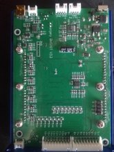
Actual Steve, yes I did and I opened the unit up to have a better clue about the grounding / neutral issue. Funny enough there is already a diode (D21) inside the chargery that links the external power supply ground to the pin 1, maybe not enough to run three amps for the relays but it is there.
Then there are two Mosfet M1 and M2 that seem to be used as voltage regulator. the input capacitor is 100V so the mention of max 55Volt input voltage might have been correct.
The current to power the device is going thru wire 1- and wire 16+ . The drop over each length of wire measured from the connector to the battery terminal is 2 mV. So that does not explain the -58 mVolt displayed on cell 16.
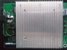
I found no connection between the case of the BMS and the neutral or for that matter any terminal of the BMS so I am not sure what is up with the warning. The case is floating. Maybe chargery means that you should not lay the case over the terminals to avoid to short the batteries or maybe afraid capacitive inductive discharge??? If so you would think they would ask you to ground the case so i works as Faraday cage.
There is a small tape between the outside of the USB plug and the case. Maybe to isolate ?
Anyhow that is all good with me.
Jason asked me to ship it to him for recalibration but since that would be on my cost. Maybe chargery is pun intended. No I did not mean that , he seems like a nice person.
I rather return the unit thru ebay to the seller to stay insync with the return / warranty of ebay.
I noticed that on ebay the MS16T is not available anymore (sold out). Not sure what to think about that, maybe pulled of the market?
Everybody wants to make this work , and would love to make it work even with the limitations of the product. These huge difference between what is measured and displayed does not bode well for the quality of the product.
Even if there is only 2 mV drop over the power leads it is still bad practice to not separate the measuring leads from the power leads.
The current sensor wires are not related to the ground either.. seems that chargery used a separate chip Q3 to measure it.
It would be better if Jason would publish the calibration software so that at least the people who can forgive the product and like to mess around have a fighting chance.
Ultimately this thing is related to the safety of your battery bank and potential a fire safety hazard if it does not function 100%.
Johan
Then there are two Mosfet M1 and M2 that seem to be used as voltage regulator. the input capacitor is 100V so the mention of max 55Volt input voltage might have been correct.
The current to power the device is going thru wire 1- and wire 16+ . The drop over each length of wire measured from the connector to the battery terminal is 2 mV. So that does not explain the -58 mVolt displayed on cell 16.
I found no connection between the case of the BMS and the neutral or for that matter any terminal of the BMS so I am not sure what is up with the warning. The case is floating. Maybe chargery means that you should not lay the case over the terminals to avoid to short the batteries or maybe afraid capacitive inductive discharge??? If so you would think they would ask you to ground the case so i works as Faraday cage.
There is a small tape between the outside of the USB plug and the case. Maybe to isolate ?
Anyhow that is all good with me.
Jason asked me to ship it to him for recalibration but since that would be on my cost. Maybe chargery is pun intended. No I did not mean that , he seems like a nice person.
I rather return the unit thru ebay to the seller to stay insync with the return / warranty of ebay.
I noticed that on ebay the MS16T is not available anymore (sold out). Not sure what to think about that, maybe pulled of the market?
Everybody wants to make this work , and would love to make it work even with the limitations of the product. These huge difference between what is measured and displayed does not bode well for the quality of the product.
Even if there is only 2 mV drop over the power leads it is still bad practice to not separate the measuring leads from the power leads.
The current sensor wires are not related to the ground either.. seems that chargery used a separate chip Q3 to measure it.
It would be better if Jason would publish the calibration software so that at least the people who can forgive the product and like to mess around have a fighting chance.
Ultimately this thing is related to the safety of your battery bank and potential a fire safety hazard if it does not function 100%.
Johan
Attachments
Last edited:
Steve_S
Offgrid Cabineer, N.E. Ontario, Canada
I know that Jason took a LOT of info from the forum posts, issues & problems along with many suggestions & ideas from us here and has been working very hard on a new Series of BMS - the "P" Series which they were in the midst of hard testing prior to CNY. They were "supposed" to be released prior to CNY but were not... I dunno why, maybe more tweaks needed or just timing due to CNY.Actual Steve, yes I did and I opened the unit up to have a better clue about the grounding / neutral issue. Funny enough there is already a diode (D21) inside the chargery that links the external power supply ground to the pin 1, maybe not enough to run three amps for the relays but it is there.
Then there are two Mosfet M1 and M2 that seem to be used as voltage regulator. the input capacitor is 100V so the mention of max 55Volt input voltage might have been correct.
The current to power the device is going thru wire 1- and wire 16+ . The drop over each length of wire measured from the connector to the battery terminal is 2 mV. So that does not explain the -58 mVolt displayed on cell 16.
I found no connection between the case of the BMS and the neutral or for that matter any terminal of the BMS so I am not sure what is up with the warning. The case is floating. Maybe chargery means that you should not lay the case over the terminals to avoid to short the batteries or maybe afraid capacitive inductive discharge??? If so you would think they would ask you to ground the case so i works as Faraday cage.
There is a small tape between the outside of the USB plug and the case. Maybe to isolate ?
Anyhow that is all good with me.
Jason asked me to ship it to him for recalibration but since that would be on my cost. Maybe chargery is pun intended. No I did not mean that , he seems like a nice person.
I rather return the unit thru ebay to the seller to stay insync with the return / warranty of ebay.
I noticed that on ebay the MS16T is not available anymore (sold out). Not sure what to think about that, maybe pulled of the market?
Everybody wants to make this work , and would love to make it work even with the limitations of the product. These huge difference between what is measured and displayed does not bode well for the quality of the product.
Even if there is only 2 mV drop over the power leads it is still bad practice to not separate the measuring leads from the power leads.
The current sensor wires are not related to the ground either.. seems that chargery used a separate chip Q3 to measure it.
It would be better if Jason would publish the calibration software so that at least the people who can forgive the product and like to mess around have a fighting chance.
Ultimately this thing is related to the safety of your battery bank and potential a fire safety hazard if it does not function 100%.
Johan
I cannot speak specifically to the BMS16 or 24 models as I use the BMS8T's which are far better behaved under Firmware 4.04 and by using the external power source port & ISO board between the DCC & BMS.
Chargery is NOT the only BMS that makes use of the sense leads as a power source as well. This is one point I never particularly liked BUT it has the option of external power source which some others do not. These were NOT Originally intended for ESS Usage, they were more aimed at the LEV segment. The new series is more intended for ESS and accomodating larger capacity cells (>100AH) like we use.
EDIT:
I should add, we recently had a couple of BMS issues arise which took a lot of folks, including manufacturers on a side trip of troubleshooting. The BMS Harness itself turned out to be a culprit in bad readings, the crimped ends in the plug itself were screwed up and not secure resulting in very erroneous readings. It is very important to make sure that ALL connections are clean, secure from the cell terminals, busbars, wires, right across the board. This includes checking each BMS wire lead from ring terminal to plug terminal end. One single messed up lead can through the whole things out of and create all sorts of erroneous issues.
Last edited:
I will have to try, I assume it should since that power comes thru the measurement wires.. Since it has a switch mode power supply 1 amp at 12 volt is 250mAmp at 48 volt. I am using opto DC SSRs but if you would use 2 x 3 Amp coil relays it would add up pretty quick thru those small wires / connectors.
I have not looked, forgot what devices were used to power the relays, maybe I am wrong with the two mosfets that I think are the power supply.
I have not looked, forgot what devices were used to power the relays, maybe I am wrong with the two mosfets that I think are the power supply.
shavermcspud
Solar Enthusiast
- Joined
- Mar 12, 2020
- Messages
- 581
@joeblack5 that's not correct, its powered from cell 1 and 8 not 1 and 16 try it yourself, mine runs fine from just an 8s pack using just the first set of balance leads on a 16t model without external power. Maybe yours is different?
I have done a full tear down on mine and parasitic draw without a DC-disconnect is 150ma on standby between cell one - and 8 +
I have done a full tear down on mine and parasitic draw without a DC-disconnect is 150ma on standby between cell one - and 8 +
shavermcspud
Solar Enthusiast
- Joined
- Mar 12, 2020
- Messages
- 581
That is odd, I wonder if we have different board revisions?Interesting , thanks for that discrepancy, just went down to verify, mine must be different.. 56mA from cell 16, 0.06 mA from cell 8/9
That is measured with balancing of and display on.
Maybe Bob. If a software issue can cause 58mVolt difference on one cell then there is a big problem. Besides putting the thing together I have spent now about 6 hours on researching / reading and measuring., getting tired of it
If Jason would have told me that it was a software issue and a known software bug then he would not have asked to ship it back for re-calibration.
i am just trying to add to the knowledge base a little bit before I ship it back.
I realize it is not that easy to measure something correctly in the 2 mVolt range and I can appreciate that. 5mV must be doable . Some people over here have way bigger differences. Cell 16 draws a lot of attention.
There are four mux CD4052B each having 4 differential channels. So 4 pieces could handle 16 cells.
I would hope that these outputs go to a differential amplifier and from there to an ADC . Then there is that the top eight cells are to high for a normal opamp so there has to be a second " neutral" reference to measure the cells 8 to 16. an isolation amplifier would have been nice.
Maybe chargery did something completely different.
making an essential hardware problem go away with software is not a good thing.
I like the separate charge / discharge relay outputs.. It would have been cool to have another one that can do load diversion.
Bob B
Emperor Of Solar
- Joined
- Sep 21, 2019
- Messages
- 8,850
I'm not saying the update will fix the voltage problem .... I have a BMS8T .... not a 16. After changing to external power and getting to 4.04, it is working very well. The furthest off I have seen any of the cell voltages is 8 mv.Maybe Bob. If a software issue can cause 58mVolt difference on one cell then there is a big problem. Besides putting the thing together I have spent now about 6 hours on researching / reading and measuring., getting tired of it
If Jason would have told me that it was a software issue and a known software bug then he would not have asked to ship it back for re-calibration.
i am just trying to add to the knowledge base a little bit before I ship it back.
I realize it is not that easy to measure something correctly in the 2 mVolt range and I can appreciate that. 5mV must be doable . Some people over here have way bigger differences. Cell 16 draws a lot of attention.
There are four mux CD4052B each having 4 differential channels. So 4 pieces could handle 16 cells.
I would hope that these outputs go to a differential amplifier and from there to an ADC . Then there is that the top eight cells are to high for a normal opamp so there has to be a second " neutral" reference to measure the cells 8 to 16. an isolation amplifier would have been nice.
Maybe chargery did something completely different.
making an essential hardware problem go away with software is not a good thing.
I like the separate charge / discharge relay outputs.. It would have been cool to have another one that can do load diversion.
From other posts I have seen, the 16 does seem to have more deviation in cell voltage readings for some reason.
The update corrects the voltage bouncing around so much and is easier to tell what you've got .... but utilizing the external power made the most difference for me .... So, I am just saying it is a good idea to get to the latest software .... which is easy to do ... and then decide what to do from there.
The first 8 cells work well for me also. to be honest.. if the software update would make 58 mV disappear then I would fee cheated unless there is a revision comment that the 4.00 software had a bug with cell 16.
I will keep following chargery and see if the future comes out less troublesome.
I will keep following chargery and see if the future comes out less troublesome.
Similar threads
- Replies
- 21
- Views
- 968
- Replies
- 7
- Views
- 513
- Replies
- 4
- Views
- 565
- Replies
- 12
- Views
- 1K
- Replies
- 11
- Views
- 670