How about a link? Something of actual value.......If you use high current active balancers and a good BMS you can series connect your pack and it will top balance during normal use.


You are using an out of date browser. It may not display this or other websites correctly.
You should upgrade or use an alternative browser.
You should upgrade or use an alternative browser.
Another Top Balance Screwup
- Thread starter Luthj
- Start date
Hedges
I See Electromagnetic Fields!
- Joined
- Mar 28, 2020
- Messages
- 21,031
Is something like that an option for parallel top balancing cells?
Looks like it:
| Output DC | 0~12V Adjustable |
| Output DC | 0~100A Adjustable |
20x the current of a 5A supply, only a few times the price.
I wouldn't bother with that unless doing many banks. For a one-off build I'd use a 7A supply I happen to have, which has remote sense so it could zero IR drop in the leads.
Immortal Lu
New Member
- Joined
- Feb 24, 2021
- Messages
- 5
I don't recall now, around 14v I think. The charger is designed to be used with a bms, which I do not have yet. It shut off the charge current after the battery exceeded 14.6V.One of the reasons I would recommend using a relatively inexpensive hobby type charger to charge cells, they will automatically shut down when cells are fully charged. What was the voltage on the power supply?
GXMnow
Solar Wizard
- Joined
- Jul 17, 2020
- Messages
- 2,738
Do those power supplies current limit at 100 amps? Is the current limit adjustable? To do this right, you want Constant Current until the voltage hits 3.5 (or whatever), and then transition to Constant Voltage and stay at the fixed voltage as the current falls away. If we wanted the best accuracy, it would be very nice to have a sensor on each cell, and disconnect them as each cell drops below 0.02C rate. This way you are not putting any extra stress on the cells. 0.1 ohm resistors are not too hard to get. I found 1% tollerance 2 watt ones for cheap on Amazon. Parallel 5 of them for each cell, puts it at 0.02 ohms and 10 watts. If you had one on each cell, the 0.02C rate of a 280 AH cell is 5.6 amps. 5.6 amps on a 0.02 ohm resistor is .112 volts, and just 0.6272 watts. They won't run very warm at all. If our desired cell voltage is 3.65, then we can set the power supply to 3.762 volts. Have a comparator hold a relay in until the voltage across the resistor fall below 0.112 volts. The 10 watt 0.02 ohm resistor groups will handle up to 22 amps before they exceed their ratings, so as long as the power supply limits to 20 amps per cell in parallel, this should work just fine. If I have to balance a bunch of large cells, this is a good way to go. Each cell just needs a relay, shunt resistor, and a comparator.
This is what I did and recommend as well. Just set your inverter change/float voltage for whatever the pack voltage is when the first cell gets to 3.4v (or whatever). Come back after a few days and reset that voltage. After a few cycles it should be balanced and you can remove the active balancer.The last few packs i have set up i have connected straight up in series and used an active balancer on the first few charge cycles - this has worked fine. (this is with Sinopoly and Winston cells, i haven’t used EVE/Lishen)
This fights the impatience issue because a) you only build the pack once and in it's final form and b) you can use it immediately without delay, just with a slightly diminished capacity.
But you guys are right, it's a higher iq plan so not much help to those busting batteries due to error.
Are you willing to enlighten us as to what you are using for an active balancer?This is what I did and recommend as well. Just set your inverter change/float voltage for whatever the pack voltage is when the first cell gets to 3.4v (or whatever). Come back after a few days and reset that voltage. After a few cycles it should be balanced and you can remove the active balancer.
Sure, this one: https://www.amazon.com/Equalizer-Ba...rds=active+balancer+24s&qid=1614871692&sr=8-1Are you willing to enlighten us as to what you are using for an active balancer?
I assume that's what everyone is using these days due to it actually working. 2A was sufficient for my 2P24S 280ah Eve pack but if I were doing more, and when I do a larger one, I'll probably get the 5A or 10A version.
If I could make one improvement on this balancer it would be to set a minimum voltage, so that I could have it only balance over 3.39V.
GXMnow
Solar Wizard
- Joined
- Jul 17, 2020
- Messages
- 2,738
The balancer zorlig linked is basically the balancer section of my JK (Heltec) BMS with the "Super Capacitor" active balancing. I am using this unit
 www.aliexpress.com
I do have to say, it works great and will pull the cells into balance in just a couple days, if there is no charge current or load on the pack. More about that later. The one I have can pull up to 2 amps from the highest voltage cell, and then push 2 amps into the lowest voltage cell. The one limitation is that it is only ever pulling or pushing current to just one cell. On a 4S pack, that is not a big limitation, but on a 14S or 16S 48 volt system, it will take longer to pull them all in. I still had to do a bit of manual balance before I assembled my pack because I was connecting the cells into a 2P configuration. I had to be sure that both strings were near perfectly matched or it would have pulled crazy currents between the cells. But once I had the pack all built up, I intentionally pulled down 4 cells with a 12 volt inverter, and then turned on the active balancing and watched it pull them back in to balance. NMC cells do act a bit different than LFP cells. The voltage on these does change faster with state of charge than it will on LFPs. But pulling the cells to the same voltage is still the right thing to do. With a 0.4 volt difference on my 360 amp hour pack, it took about 40 hours to get those 4 low cells back up to within 0.005 volts of the high cells. As my pack charges through the knee (at 60% charge on NMC cells) I do sometimes see the voltages spread to 0.005 (5 mv) but they converge again once past the knee, so I set the balancer to only move power when it sees a 6 mv (0.006 volt) difference. At that setting, I rarely ever see the balancer do anything. On LFP cells, I would expect the balancer to sit and do nothing when the pack is between 30% and 80% charged as the discharge curve on LFP cells is so flat in that area. When it gets above 85% or so, the top state of charge cell will start to climb in voltage, and the balance will start pulling 2 amps from that cell. But it can only do that for a bit less than half the time. So figure an average of 1 amp being drawn from the first cell entering the knee. It will then push 2 amps into the lowest voltage cell. If there are several that are very close, it will spread it out and push into a few cells, but still only one at a time. If you have 3 at the same voltage, each would get the 2 amps, for just 1/6th of the time. If one cell is lagging behind, it will get the full 2 amps for 1/2 the time. So if your pack is far out of balance, it can still take a long time to pull it in.
www.aliexpress.com
I do have to say, it works great and will pull the cells into balance in just a couple days, if there is no charge current or load on the pack. More about that later. The one I have can pull up to 2 amps from the highest voltage cell, and then push 2 amps into the lowest voltage cell. The one limitation is that it is only ever pulling or pushing current to just one cell. On a 4S pack, that is not a big limitation, but on a 14S or 16S 48 volt system, it will take longer to pull them all in. I still had to do a bit of manual balance before I assembled my pack because I was connecting the cells into a 2P configuration. I had to be sure that both strings were near perfectly matched or it would have pulled crazy currents between the cells. But once I had the pack all built up, I intentionally pulled down 4 cells with a 12 volt inverter, and then turned on the active balancing and watched it pull them back in to balance. NMC cells do act a bit different than LFP cells. The voltage on these does change faster with state of charge than it will on LFPs. But pulling the cells to the same voltage is still the right thing to do. With a 0.4 volt difference on my 360 amp hour pack, it took about 40 hours to get those 4 low cells back up to within 0.005 volts of the high cells. As my pack charges through the knee (at 60% charge on NMC cells) I do sometimes see the voltages spread to 0.005 (5 mv) but they converge again once past the knee, so I set the balancer to only move power when it sees a 6 mv (0.006 volt) difference. At that setting, I rarely ever see the balancer do anything. On LFP cells, I would expect the balancer to sit and do nothing when the pack is between 30% and 80% charged as the discharge curve on LFP cells is so flat in that area. When it gets above 85% or so, the top state of charge cell will start to climb in voltage, and the balance will start pulling 2 amps from that cell. But it can only do that for a bit less than half the time. So figure an average of 1 amp being drawn from the first cell entering the knee. It will then push 2 amps into the lowest voltage cell. If there are several that are very close, it will spread it out and push into a few cells, but still only one at a time. If you have 3 at the same voltage, each would get the 2 amps, for just 1/6th of the time. If one cell is lagging behind, it will get the full 2 amps for 1/2 the time. So if your pack is far out of balance, it can still take a long time to pull it in.
Now you still need to understand the other limit here. If you are charging at just 5 amps, and you have one cell that is already into the knee, the balancer will only be able to pull the 1 amp average from it. So it is still getting 4 amps of effective charge current. So it can still start to run, and the balancer can't stop it. The BMS function will kick in and shut off charging at the set over voltage set point though. And while in over volt shut off, the balancer can still work to pull that cell down. In on grid backup mode, I still charge / discharge my pack at over 25 amps, and could hit 140 amps max if I fully load the system in a power failure. So that tiny 2 amps of balance current can't do much. If you do plan to run the system so it goes into the top knee on every charge cycle, you may have issues keeping the cells all in line. As LFP cells go into the knee, the voltage can start to change very quickly, especially at higher charge currents. While I am on grid (99.9% of the time), my battery bank does get a 10 hour rest, but it is at 50-60% charge after it runs my house for the peak power time each evening, until the sun comes up the next day. During that 10 hours, the balancer can pull and push power around and balance the cells while there is not charge or discharge current. This might not help much on LFP as they have virtually no voltage difference from 35% to 70% state of charge. You would want the resting/balancing time to be at near full charge to do a "top balance". My setup finishes charging from the sun around 3 pm, and starts exporting power at 4 pm, so just one hour in that state each day. With well matched cells, this is working perfectly, but with bulk Chinese LFP cells, I am not as sure this balancer would be able to keep up with drift. If (when) I go to a large LFP bank, I will not charge to over 3.35 volts each day, and I will monitor it close for a while to see if the voltages start to stray. I really do like the way the active balancer works, and will use one like this again, but with how LFP can run away at the top, I may also add a second resistive balancer that can kick in a large 10 amp draw resistor when a cell is going too high. That is throwing away some power, but that is way better than having a run away cell causing the BMS to shut down the system. and 10 amps at 3.5 volts is just 35 watts for each cell going too high while charging from solar.
The better matched the cells are, the less work the balancer will need to do. Some systems with good cells have no problem with having a BMS that only monitors the cells, or has even just a tiny 30 ma passive balance during the top of charging.
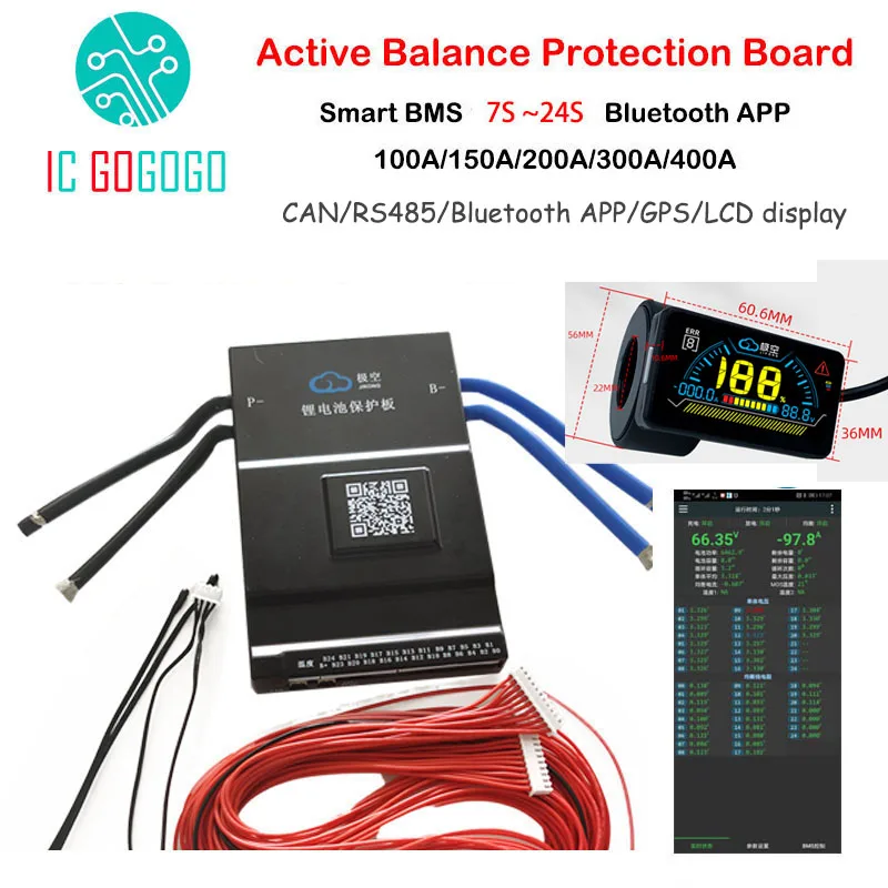
7.5US $ 25% OFF|1a/2a Active Balance Battery Protection Board Smart Bms 7s ~ 24s 100a 150a 300a Can Rs485 Gps App Lifepo4 Li-ion Lto Jk 16s 20s - Battery Accessories & Charger Accessories - AliExpress
Smarter Shopping, Better Living! Aliexpress.com
Now you still need to understand the other limit here. If you are charging at just 5 amps, and you have one cell that is already into the knee, the balancer will only be able to pull the 1 amp average from it. So it is still getting 4 amps of effective charge current. So it can still start to run, and the balancer can't stop it. The BMS function will kick in and shut off charging at the set over voltage set point though. And while in over volt shut off, the balancer can still work to pull that cell down. In on grid backup mode, I still charge / discharge my pack at over 25 amps, and could hit 140 amps max if I fully load the system in a power failure. So that tiny 2 amps of balance current can't do much. If you do plan to run the system so it goes into the top knee on every charge cycle, you may have issues keeping the cells all in line. As LFP cells go into the knee, the voltage can start to change very quickly, especially at higher charge currents. While I am on grid (99.9% of the time), my battery bank does get a 10 hour rest, but it is at 50-60% charge after it runs my house for the peak power time each evening, until the sun comes up the next day. During that 10 hours, the balancer can pull and push power around and balance the cells while there is not charge or discharge current. This might not help much on LFP as they have virtually no voltage difference from 35% to 70% state of charge. You would want the resting/balancing time to be at near full charge to do a "top balance". My setup finishes charging from the sun around 3 pm, and starts exporting power at 4 pm, so just one hour in that state each day. With well matched cells, this is working perfectly, but with bulk Chinese LFP cells, I am not as sure this balancer would be able to keep up with drift. If (when) I go to a large LFP bank, I will not charge to over 3.35 volts each day, and I will monitor it close for a while to see if the voltages start to stray. I really do like the way the active balancer works, and will use one like this again, but with how LFP can run away at the top, I may also add a second resistive balancer that can kick in a large 10 amp draw resistor when a cell is going too high. That is throwing away some power, but that is way better than having a run away cell causing the BMS to shut down the system. and 10 amps at 3.5 volts is just 35 watts for each cell going too high while charging from solar.
The better matched the cells are, the less work the balancer will need to do. Some systems with good cells have no problem with having a BMS that only monitors the cells, or has even just a tiny 30 ma passive balance during the top of charging.
Bob B
Emperor Of Solar
- Joined
- Sep 21, 2019
- Messages
- 8,845
My 190 AH cells balanced just fine without parallel top balancing with the 1.2 A balance current built into the Chargery BMS I am using even with a 2P4S configuration. Once the pack hit the knee, I reduced the charge rate to only about 2A. I went right up to 3.65 the first charge, but have since reduced the top end to 3.5 V.
The pack may have spent a little more time in the upper knee using the slow charge in the knee, but still only took a couple of hours or less ..... and I really doubt that amount of time held in the knee did any harm.
The pack has stayed well balanced thru the whole range.
I suspect the 190 cells are a little better matched than the commodity 280's being used by so many now, but series balancing worked fine for me.
I am still debating whether or not to re-configure the pack to 24V .... will be interesting to see what happens if I do that.
AlexanderKristiansen
New Member
- Joined
- Mar 18, 2020
- Messages
- 96
Yeah, I guess I get it if people are doing it to overcome crappy leads, but that seems like a really poor and risky solution to a simple problem. Just make some proper leads and don’t risk cooking your cells.
Does anybody know if there is a tutorial how to make proper leads for a power supply?
Hedges
I See Electromagnetic Fields!
- Joined
- Mar 28, 2020
- Messages
- 21,031
Does anybody know if there is a tutorial how to make proper leads for a power supply?
That's more like the basic knowledge or understanding you should have before attempting DIY of any electrical circuits.
Learn Ohm's Law and do some calculations using it related to the application. Then you can design power supply leads.

Ohm's law - Wikipedia
Power supplies typically accept ring terminals or banana plugs. Find the appropriate terminal/connector. Crimp/solder it to a wire of sufficient gauge. for 10A I would do 12-10AWG for example. You want less than 20mV drop in your cables at the rated current in my opinion (both cables combined).
Hard to mess it up if you have the proper stuff.Does anybody know if there is a tutorial how to make proper leads for a power supply?
10 gauge wire if you don't already have some extra. You really just need 2-4 feet of each color depending on how far you need to run. Shorter is less voltage drop, but longer is nice to keep workspace organized. With 10 gauge and running under 10a, 4 foot leads are fine.
decent quality ring terminals (kit below but you can just buy a pack of 5 or 10). Make sure the ring diameter is big enough for power supply terminal posts.
Amazon.com: 270 PCS Heat Shrink Wire Connector Kit Electrical Insulated Crimp Marine Automotive Terminals Set: Home Improvement
Buy 270 PCS Heat Shrink Wire Connector Kit Electrical Insulated Crimp Marine Automotive Terminals Set: Ring - Amazon.com ✓ FREE DELIVERY possible on eligible purchases
www.amazon.com
quality crimpers
optional heat gun (or just use a flame if it's a one-off thing)
I don't understand how someone would "walk away" from a pack that is charging. Top balancing is so simple and if cells are at high SOC, should take an hour, tops. I am so glad that folks are using LiFePO4, because if this was NMC or NCA, their house would be burned down right now. I just cannot understand how someone would make this mistake.
If someone walks away from a charging pack during top balance, they shouldn't be touching these batteries. All batteries are dangerous, and the fact that a person could have such negligent behaviors makes me question what other issues they will have. I could easily see them destroying the FET's on their BMS because they "accidentally" forgot to use a precharge capacitor on their 6kW inverter.
I do not understand. How would someone make this mistake? This thread makes me cringe.
And the gas creation that caused the initial swelling from this overcharge event is irreversible. This will change the composition of the electrolyte, and the internal resistance of the cells is now higher. Ensure that your friend fully understands this. I would throw those cells in the garbage because they are ruined.
Hedges
I See Electromagnetic Fields!
- Joined
- Mar 28, 2020
- Messages
- 21,031
There are lots of mysteries in electricity and chemistry.
If someone has to purchase a power supply to top-balance, good chance they are unfamiliar with series, parallel, ohms law, watts.
Unlike household plumbing, where you can see leaks and the biggest mystery is corrosion at interface between steel and copper, nothing is visible until smoke or swelling appears.
Being comfortable with math and learning to apply electrical equations is a prerequisite.
Then, understanding the charge curve of LiFePO4, allowed operating range, and the inevitable appearance of "runners" because there will always be imbalance. If someone understands those aspects of the battery and how CV setting of power supply and cell-level monitoring and disconnect function of BMS protect it, then they can tackle the project.
Inrush is another difficult topic. We see how people can buy a two-position switch and resistor or add a separate precharge button. What I don't see is a bundled 2-position precharge switch - if necessary for lithium batteries you'd think it would be a standard offering.
It wasn't needed with lead-acid and inverters like mine. I don't think it is part of the system using my brand of inverters and off the shelf compatible lithium batteries (48V or 400V depending on inverter.)
I've seen lots of issues with soft-start circuits designed into electronics. The problem seemed to be downstream circuits turning on before precharge was complete (and FETs that perform the function being "saturated" or on hard.) That requires either an enable signal or known delay.
A BMS ought to be designed to handle charging of capacitors. It could turn on the gate slowly to limit maximum current, and give up if they overheat. Or, shut off if over-current and use another FET + resistor to attempt precharge. Ideally, BMS + fuse could handle anything (besides extreme overvoltage) with no damage except for blown fuse.
AlexanderKristiansen
New Member
- Joined
- Mar 18, 2020
- Messages
- 96
That's more like the basic knowledge or understanding you should have before attempting DIY of any electrical circuits.
Learn Ohm's Law and do some calculations using it related to the application. Then you can design power supply leads.
Ohm's law - Wikipedia
en.wikipedia.org
There is no need to be rude. I have imported battery cells from China and built my own battery-pack with a BMS, I have more than basic knowledge. Your reply doesn't give me any information I need. I know the size of the wires, I am just wondering what type of connectors the power supply needs. Be a little less condescending and a little more helpful and the world will be a better place.
John Frum
Tell me your problems
- Joined
- Nov 30, 2019
- Messages
- 15,233
That depends on the power supply.Your reply doesn't give me any information I need. I know the size of the wires, I am just wondering what type of connectors the power supply needs.
What type of connectors does your power supply have?
AlexanderKristiansen
New Member
- Joined
- Mar 18, 2020
- Messages
- 96
That depends on the power supply.
What type of connectors does your power supply have?
Its this power supply:
https://www.amazon.com/gp/product/B07ML2MP9Q/ref=ppx_od_dt_b_asin_title_s00?ie=UTF8&psc=1
Doesn't look like it using ring terminals?
ArthurEld
Solar Wizard
You need fork terminals. The yellow ones with 10 AWG wire. The other end will need a ring terminal with M6 hole.Its this power supply:
https://www.amazon.com/gp/product/B07ML2MP9Q/ref=ppx_od_dt_b_asin_title_s00?ie=UTF8&psc=1
Doesn't look like it using ring terminals?
Like this - https://www.amazon.com/Glarks-240pc...0603&sprefix=fork+crimp,industrial,208&sr=8-9
Similar threads
- Replies
- 34
- Views
- 768
- Replies
- 32
- Views
- 2K
- Replies
- 10
- Views
- 804
- Replies
- 11
- Views
- 1K