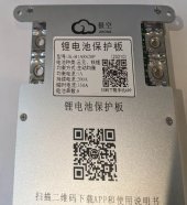
The BMS arrived yesterday evening. It has a paper label stating it to be a 'JK-B1A8S20P', but it is a heating circuit model per Nami's description in
post #1.
Although labeled for 1A balance current, it might actually be the "2A" model, now for sale here:
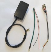
2A version with heat, at Aliexpress "Hankzor BMS Store". I can test to obtain that limit, using an appropriate resistor load on just one cell within the managed battery pack. the package came with a dual temperature sensor interface already attached on the BMS. 3 accessory attachments were also provided:
- A BMS push-button power switch;
- A small 'monitor' device;
- The new heater port cable assembly.
I did not receive any device or cable which can utilize the RS-485 port. A GPS port is also present, but J-K has not yet created a GPS device to use it. The 'push-button power switch' and the 'monitor device' both connect to the same 6-pin header port on the BMS unit. They can't be connected at the same time. The power switch cable contains 4 wires, while the monitor uses all 6 wires BMS port pins.
The heater port cable provides a small black wire, presumably a "ground", and a red cable, presumably running at battery voltage. I don't know whether it is actually necessary to connect those wires to anything, Or whether they are provided as "test leads" for optional use while the heater interface is being used. The other 4 wires, green in color, are bonded to a single shared lug. I suspect this to be the shared "switched" heater power link, although the wire color is somewhat misleading to a resident of the USA.
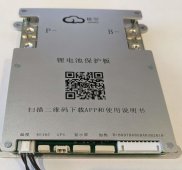
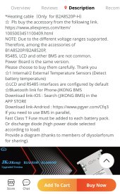
I can test for correct wiring of this interface, if Nami does not have time to reply here. I can do some testing on Monday. 3 attached photos show the accessories, the somewhat incorrect label, and the front of the BMS, with ports shown. (I left the monitor upside down in the photo, the LED screen is shiny and there is a small button on it). Android App installation from the QR code was easy and uneventful (assuming that Version 4.6.5 was the one to select).


")