diy solar

diy solar

How does your inverter deal with ground.

re Deye, Sol-Ark, SunSynk

Terms:
Inverter Module refers to the electronic parts that converts DC to AC power.
Inverter (Deye, Sol-Ark, SunSynk) refers to the whole product.
GRID = refers to terminal and wires connected to it.
LOAD = refers to terminal and wires connected to it.
Grid = refers to the power company

These Inverters have internal Bypass (or Passthrough) relays that connects Inverter Module, LOAD and GRID together during normal operation.
View attachment 109443
And disconnects GRID (from LOAD) during a utility outage. LOAD is now powered solely by Inverter Module.

When GRID is disconnected, the two LOAD lines are now floating and Inverter becomes an ungrounded power supply.
These two lines could be safely at ±120V from GND, but could drift to >1000v from GND.
When it does, could discharge to the grounded chasis through some other means causing damage to Inverter, to appliance, to occupant touching appliances.

It is recommended that during an outage (or when Inverter is used in UPS mode), it is to bond one of the LOAD wires (preferably the one labeled as N or L2) to GND, so one of the wire would be 0V, and the other would then be 240V never beyond. Now the Inverter is a ground Power Supply and neither wires have voltage potential that exceeds dielectric strength of the electronic parts, wire insulation, etc...

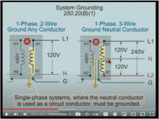
Watch video by SunSynk on bonding during a power outage using ATS240V signal.
(This signal does not seem available on the 12K, 15K inverter versions. Maybe these models come with a different bonding method?)
View attachment 109447

When Utility returns, Inverter:
1. waits for "Reconnection Time", then
2. deactivates ATS240V signal and connects GRID with LOAD
Everything reverts back to normal.


HERE IS THE PROBLEM
If your Inverter was wired as suggested by Keith's video, there is this chance that the external relay is much slower than the internal relay, and when internal relay connects GRID with LOAD, one of LOAD terminal is still connected to GND causing a short. DO NOTE: the Internal Relays are being powered (relying on the power of electricity to move the arm) while the external relay is being unpowered (relying on the strength of the spring to move the arm)

QUESTION:
Can we use a resistive load, say a 100w 1kΩ (replace the BLUE WIRE on the last diagram with a resistor) to complete the bonding of this external relay to GND? This way, if the relay is slower than the internal relay, it will not cause a short.

Unfortunately, this is a weak grounding.
As long as you are bonding the same conductor that is bonded by the grid. There won't be any shorting issues. There will just be a double bond, for the time it takes the second relay to react.
 
Folks, When setting up an inverter, one of the more important safety things to get correct is the grounding and the neutral-Ground bond.
  • All of the inverters have a grounding lug
  • All of the inverters have a ground connection on the AC out.
  • Some inverters have an AC in and when they do they have a ground connection on the input.
Sadly, the information provided in many manuals is nearly non-existent when it comes to how it handles ground internally.

Are the two (or three) grounds tied together?
Is there a neutral-ground bond?
If there is an AC-IN, does it change the neutral-ground bond when getting power from the AC-in?

I have started to try and collect this type of information for various inverters. Once I get information on several of them I will put it all into a resource and post it.

How does your inverter handle internal ground? If you send me the make/model of your inverter, I will add it to the resource.

The next 3 posts are examples of what I envision for each page of the resource.
Victron multiplus, 24/70 -3000W ….thx .J.
 
As long as you are bonding the same conductor that is bonded by the grid. There won't be any shorting issues. There will just be a double bond, for the time it takes the second relay to react.
Unfortunately it is not.

Some Deye (EU) models have the terminals labeled L N PE (which makes it appear it is fine to ground the N line).
But in some countries, the terminals are labeled L1 L2 PE instead having the exact same wiring as the EU versions.
And these L lines are both hot 120VAC (relative to ground, earth, Utility's N)

1661906950241.png

In Keith's video it is obvious he was grounding LOAD's L2 to ground during an outage.
 
Unfortunately it is not.

Some Deye (EU) models have the terminals labeled L N PE (which makes it appear it is fine to ground the N line).
But in some countries, the terminals are labeled L1 L2 PE instead having the exact same wiring as the EU versions.
And these L lines are both hot 120VAC (relative to ground, earth, Utility's N)

View attachment 109449

In Keith's video it is obvious he was grounding LOAD's L2 to ground during an outage.
That's because Keith is only selling inverters to a market where L = 230v/240v to N & N is normally bonded to ground.
 
That's because Keith is only selling inverters to a market where L = 230v/240v to N & N is normally bonded to ground.
True.

However, we still need a real solution..

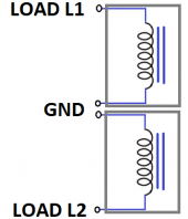
OK maybe using two transformers ~100W 220V, permanently wired directly to LOAD's L1 L2 PE as shown.
1661917912562.png
This way, L1 and L2 are guaranteed to float as near as possible to GND - albeit a "weak ground" capable of ~1A path to GND.

A single Center Tap Transformer (aka AutoTransformer) will work ONLY if the Grid's L1 N L2 are 120V-0-120V and not 120V-0-208V
 
It all depends on where you are and what equipment you are trying to use. If it's not designed for your local configuration. Then you will have to modify it to work.
Anytime you use a non US inverter in the US, and want a grid connection. The only safe way is with an isolation Transformer.
 
True.

However, we still need a real solution..

OK maybe using two transformers ~100W 220V, permanently wired directly to LOAD's L1 L2 PE as shown.
View attachment 109469
This way, L1 and L2 are guaranteed to float as near as possible to GND - albeit a "weak ground" capable of ~1A path to GND.

A single Center Tap Transformer (aka AutoTransformer) will work ONLY if the Grid's L1 N L2 are 120V-0-120V and not 120V-0-208V

I'm not convinced this will hold L1 and L2 centered about neutral.

I'm thinking of a similar issue with a setup I'm doing, 3-phase.
If a "Y" configured transformer powers a circuit, it is kept centered even if loads or primary of a driven transformer is delta. Or imbalanced.
But what I'm going to do is drive the "secondary" 120/208Y of a transformer, so its 480 delta "primary" delivers the voltage needed for my 3-phase PV inverter. (Instructions say to prevent situation where wire faulted to ground makes it 480V corner-grounded delta.)

Even if I connected a 3-phase transformer's "Y" windings to the circuit, I think that is just three high-impedance inductors. In the case of three coils on an "E" core, there may be some interaction among them.

Of course, if the windings can't take higher than nominal voltage (120V in your case, 277V in mine), they would saturate and limit how far imbalanced the voltage could become.
 
I'm not convinced this will hold L1 and L2 centered about neutral.
Just so we are clear: I am not trying to supply a 120V-Neutral-120V like in USA's split phase.
I am trying to provide an earth ground path for L1 and L2 when in Off-grid or EPS (grid is down).


Keith (SunSynk) was doing Circuit A. But that is not safe if my Grid lines are hot (as explained previously).
So I thought of doing Circuit B. It was coincidental that this transformer method would center them around earth ground.
1661927238378.png
I thought of using two transformers because my Grid's utility is 120V-0-208V.
And with that, I cannot use a single center tap transformer (unless I could easily get 120-0-208 transformers).
If my Grid is 120v-0-120v, I will use center tap transformer (as that will provide a stronger grounded system).
Likewise center tap transformers as so easy to get. They are like a dime a dozen.
And since I am not providing Neutral for power, these small ~100W transformers will not get saturated at all.
Nor do I need them perfectly balanced. Even if I use two 240v transformers on my 120v-0-208v line, it will be fine.
But using bigger transformers would give an even stronger grounded system.

You are correct that these functions like high-impedance inductors (not as a true transformer).
And by doing so, you can clearly see those two inductors become a voltage divider with center tied to earth ground.
If using two separate transformers, it forms a not so strong grounding;
but if using a single transformer (shared core), it forms a strong grounding;
and if using thicker wires and larger core, it forms a stronger grounding.

I'm thinking of a similar issue with a setup I'm doing, 3-phase.
If a "Y" configured transformer powers a circuit, it is kept centered even if loads or primary of a driven transformer is delta. Or imbalanced.
In a 3Phase transformer with secondary as Y, the center is centered regardless of load. TRUE.
But it could be centered anywhere from earth ground 0v (if grounded), or float a few thousand volts above earth ground.
Thus, you still need to ground something on that Y. Center is best as shown.
1661926376896.png

I understand you are trying to use the Y secondary to get a 3Phase Delta.
However, these two windings are isolated from each other.
Even if your Y is grounded, you still need to ground the Delta.
 
Last edited:
The above discussion shows why so many users and installers are uncertain as to the correct grounding procedure. My impression is a significant number of Deye derived inverters are installed with just the earth cable connected to the chassis which feeds into the grid earth, leaving no earth when in UPS mode. The close up photos showing which terminals the earth neutral bond goes to is very helpful,I kept pausing Keith's video trying to work out the terminal he was attaching to. Should the other end of the earth wire going into the relay be attached directly to an earthing rod or routed via the inverter? I have an earthing rod used by my EV charger next to where the inverter is located. I thought I could use that, would I be reestablishing my connection to the grids earthing system, which would fail an inspection, but offer protection for inverter users? Or would the EV charger not be connected to the grid earth to prevent a double earth? Do I need a second earthing rod? Is there then a problem with two rods being in close proximity?
 
I really hate the term "Earth ground". It just adds confusion to the conversation. The Earth has nothing to do with grounding, other than the Earth should be connected to the ground system just like the water service, gas piping, and metal structures. The grounding system begins at the systems N/G bond.
And everything is connected to the grounding system after it.
The grounding systems purpose is to provide a low impedance path back to the source. The impedance of the Earth varies, depending on moisture and mineral content. Using a second ground rod instead of a grounding conductor, just gives the illusion of safety.
If you want to test this. Stretch an extension cord 50' out from your house and connect the live conductor to a large nail and stick it in the Earth. Then plug the extension cord into a house outlet. It won't trip a breaker or blow a fuse. What it will do is make all of the worms come to the surface. As kids we used to do this in the morning before going fishing. (Make sure that you unplug the cord before you start collecting the worms. Picking up two at once can shock you.)

Disclaimer: for intertainment purposes only.
not recommended by me.
If try this, you do so at your own risk.
 
Last edited:
the answer is there is no “ right way “ , it depends on “ code “
in my case a 230 vac EU boat , there is no connection between DC and AC at all. , shore power protective earth just runs to direct mains electrically power units.

Hence my invertor , transfer switch triggers relay that cuts the shore lead dead ( all three lines, L,N,E) and bond N to E at the inverter
 
I really hate the term "Earth ground". It just adds confusion to the conversation. The Earth has nothing to do with grounding, other than the Earth should be connected to the ground system just like the water service, gas piping, and metal structures. The grounding system begins at the systems N/G bond.
And everything is connected to the grounding system after it.
The grounding systems purpose is to provide a low impedance path back to the source. The impedance of the Earth varies, depending on moisture and mineral content. Using a second ground rod instead of a grounding conductor, just gives the illusion of safety.
If you want to test this. Stretch an extension cord 50' out from your house and connect the live conductor to a large nail and stick it in the Earth. Then plug the extension cord into a house outlet. It won't trip a breaker or blow a fuse. What it will do is make all of the worms come to the surface. As kids we used to do this in the morning before going fishing. (Make sure that you unplug the cord before you start collecting the worms. Picking up two at once can shock you.)
My father's boss killed himself doing this back in the 60's
 
Historically where I am neutral was never actively bonded to earth , all there was was an earth rod. These houses still exist. These days the earth rod is gone and the NG bond is prevalent.

The primary purpose of the protective earth is to provide a path to flow the fuses the minute anything grounded become live.

Arguably in these RCD days it’s antiquated.
 
I really hate the term "Earth ground". It just adds confusion to the conversation. The Earth has nothing to do with grounding, other than the Earth should be connected to the ground system just like the water service, gas piping, and metal structures. The grounding system begins at the systems N/G bond.
And everything is connected to the grounding system after it.
The grounding systems purpose is to provide a low impedance path back to the source. The impedance of the Earth varies, depending on moisture and mineral content. Using a second ground rod instead of a grounding conductor, just gives the illusion of safety.
If you want to test this. Stretch an extension cord 50' out from your house and connect the live conductor to a large nail and stick it in the Earth. Then plug the extension cord into a house outlet. It won't trip a breaker or blow a fuse. What it will do is make all of the worms come to the surface. As kids we used to do this in the morning before going fishing. (Make sure that you unplug the cord before you start collecting the worms. Picking up two at once can shock you.)

Disclaimer: for intertainment purposes only.
not recommended by me.
If try this, you do so at your own risk.
In my case the RCD on the house supply would trip , or the RCD plug in the extension. Lead would trip
 
In my case the RCD on the house supply would trip , or the RCD plug in the extension. Lead would trip
Yes, that's why they are widely implemented.
They don't need a ground connection to work.
If current flows anywhere that it shouldn't, the circuit is opened. (Turned off)
 
Yes, that's why they are widely implemented.
They don't need a ground connection to work.
If current flows anywhere that it shouldn't, the circuit is opened. (Turned off)
Yes in my marina there’s 6 RCD between me on the boat and the incoming mains to the marina !!!
 
I thought of using two transformers because my Grid's utility is 120V-0-208V.
And with that, I cannot use a single center tap transformer (unless I could easily get 120-0-208 transformers).
If my Grid is 120v-0-120v, I will use center tap transformer (as that will provide a stronger grounded system).
Likewise center tap transformers as so easy to get. They are like a dime a dozen.
And since I am not providing Neutral for power, these small ~100W transformers will not get saturated at all.
Nor do I need them perfectly balanced. Even if I use two 240v transformers on my 120v-0-208v line, it will be fine.
But using bigger transformers would give an even stronger grounded system.

At first I thought you meant your utility grid was unbalanced in voltage, L2 was a bit low, 208V to ground.
But do you mean your grid is 120/208Y (L1, L2, L3 are each 120V to N and 120 degrees apart, so L1 is 208V to N)? And you get two out of three phases, L1, L2, N?

In that case the two separate transformers (inductors) are required, which I think you showed. Can't share a core because out of phase (except, some 3-phase transformers do have all three windings on a single "E" core; the way the three fields sum apparently works out.) Maybe two windings on one core (e.g. the secondary windings of 240/480 to 120/240 single-phase transformer) actually works the same, because essentially zero current is being drawn. The fraction of an amp windings will carry are just out of phase. I'll have to ponder that more, maybe SPICE.

"A single Center Tap Transformer (aka AutoTransformer) will work ONLY if the Grid's L1 N L2 are 120V-0-120V and not 120V-0-208V"

If voltages are different from winding ratio, transformer will try to balance the voltage. Voltage of transformer sags due to winding resistance, limiting how hard it tries. A 10% voltage difference would make it try pretty hard, because that is greater than the 3% or 5% "regulation" of the transformer.

If phase is different, it will also try to make current in-phase.

Saturation - I do know a thing or two about that, have been taking measurements driving chokes and inductors into saturation.

Since you are only using a single winding that is around the core on each transformer (your two windings aren't magnetically coupled), let's call them "inductors".
Saturation occurs when magnetization of the core approaches its limit, most magnetic domains have been magnetized. This occurs in proportion to the number of ampere-turns. If there were two windings with current flowing in opposite directions (a transformer), the ampere turns cancel.

When voltage is applied to a winding, V = L di/dt, or I = integral_over_time(V/L).
With 120Vrms 60 Hz applied to a winding designed for that, current rises gradually because "L" remains fairly constant. If frequency was reduced to 30 Hz or voltage increased to 240Vrms, current would approach twice as much and for most transformers it would go into saturation.
Once in saturation, current shoots up to whatever V = IR the winding resistance allows.

If a transformer is designed to carry 100A (and opposite polarity 100A in another winding), it will saturate with less than 1% of that current, something between 0.1A and 1.0A

If you used a 120W 120V transformer for this purpose, 120W / 120V = 1.0A operating current. With just one winding connected and 120V applied, it will carry something on the order of 0.01A
That may keep the two voltages within approximately +/-120V of ground; if they drift, an imbalance in current through the inductor should gently bias them back toward balanced.

Consider what happens if you get a fault between one phase and ground, even high resistance.

N or Ground is zero volts. L1 is tugged gently to zero volts. L2 is now 240Vrms. V = L di/dt, current will ramp up twice as fast. Something beyond half way through an 8 millisecond phase, current will have risen past saturation point, and L2 current will shoot up, clamping L2 voltage to ground.

I think what you are doing is using saturable inductors as voltage clamps.
But does that unceremoniously yank L2 all the way to ground, and afterwards L1 and L2 take turns doing that every phase? Or is it a bit more gradual, and re-centers?

"Even if I use two 240v transformers ..."

That would prevent saturation in this case of L1 getting grounded. It would also reduce the tendency to re-center, because drifting voltage wouldn't go as far into non-linearity.

Transformer inrush is a problem that occurs if a winding is driven with a half-cycle just before power is removed, then when power is reapplied it is driven with a second half-cycle of same polarity. The ampere-turns x time is now double, typically causing saturation.
I think when winding intended for double voltage is used (240V in your case), that is prevented; two successive phases of 120V do not exceed the magnetization of a single 240V phase.
 
What it will do is make all of the worms come to the surface. As kids we used to do this in the morning before going fishing. (Make sure that you unplug the cord before you start collecting the worms. Picking up two at once can shock you.)

Disclaimer: for intertainment purposes only.
not recommended by me.
If try this, you do so at your own risk.

Hand crank generator (e.g. from antique phone) is a recommended method.
You let go of the crank before picking up the earthworms.

Perhaps a momentary pushbutton would make for a safer AC powered Nightcrawler Stimulator.

The real pros skip the earthworm part, throw extension cord directly into the water, then go gather the fish. Just be sure to unplug cord first ...
 
In a 3Phase transformer with secondary as Y, the center is centered regardless of load. TRUE.
But it could be centered anywhere from earth ground 0v (if grounded), or float a few thousand volts above earth ground.
Thus, you still need to ground something on that Y. Center is best as shown.
View attachment 109483

I understand you are trying to use the Y secondary to get a 3Phase Delta.
However, these two windings are isolated from each other.
Even if your Y is grounded, you still need to ground the Delta.

Exactly, that is what I am trying to solve.
How can I ground the delta, so it's line to ground voltages are all approximately 277Vrms? My equipment can't take corner ground delta.

At the moment, I've kludge wired three transformers to each serve as 120/277V auto-transformer, wired as 120/208Y to 277/480Y auto-transformer. The midpoint of the "Y" is connected to neutral, which is bonded to ground.


I want to replace that with an enclosed transformer, an off-the-shelf UL listed device.
Very few transformers have 277/480Y windings. I find many with 480 delta secondary, 120/208Y primary.


Here is the issue I'm trying to address:


"STP 30000TL-US-10* 480 V / 277 V WYE: YES, 480 V Delta: YES**
* A neutral conductor connection is necessary for the 480 V / 277 V WYE. A neutral conductor connection is not necessary for the 480 V Delta.
** For connection to 480 V Delta commercial services where co-located loads may result in recurring and persistent line-to-ground faults (effectively resulting in a corner grounded Delta grid configuration), inverters must be protected from excessive line-to-ground voltages by isolating the PV system from the source(s) of the fault(s)."


I had thought of connecting a small "Y" transformer, similar to your idea. You're using two completely separate transformers, which I don't think accomplishes much (except as a saturable inductor.)
Possibly three-phase transformer on single "E" core works; if tugged off center, sum of magnetic "currents" or "potential" gets out of phase.
Resistive loads would work, but is lossy. Same goes for resistive loads on secondary of a Y-delta transformer.

One thing I think would work is if the 480V delta had center-tapped windings, 240/480V.
Grounding center of one side (high leg 240/480 delta) might still be too high a voltage.
But, what I could do is put an auto-transformer between center of one side and the opposite corner. Ground a suitable midpoint of that auto-transformer.

Right triangle, 277V hypotenuse and 240V on one side.
sqrt(277^2 - 240^2) = 138V
277V / 138V = 2.0 ratio
A single-phase transformer, 480V to 240V (e.g. typical 240/480 to 120/240) could be wired in series as auto-transformer, with 277V applied to the 480V winding and 138V coming from 240V winding. The midpoint would establish Neutral to be grounded.
Ratio isn't exact because transformer secondaries are wound a couple percent high under no-load. But good enough for my application.

However, the 120/208Y to 480 delta transformers I'm considering do not have a center tapped 480V. I would have to connect yet another transformer, 240/480V auto-transformer, to get midpoint of one side.

I was shopping for a pile of 10kVA 240/480 to 120/240V transformers. With four of them I could have done the voltage conversion and grounding of neutral. Can't find enough of same model and cheap enough.
 
Apparently grounding the virtual neutral of a Delta transformer is a thing.
Zigzag transformer is supposed to be a solution:


I'm trying to evaluate that in LTSpice because I'm having difficult wrapping my head around it. Not doing what it is supposed to, yet.


I've got more studying to do.
 
I got Zigzag transformer working in LTSpice. I had simply forgotten to couple the inductors "K1 L1 L2 0.999" etc.
I had only coupled the inductors of Wye and Delta transformer windings, not the Zigzag.

I've read that sizing it at 3% the VA rating of power transformer is sufficient for a few seconds short-circuit, to trip a breaker (sounds like I'll be better off with magnetic-hydraulic not thermal-magnetic).

My SPICE used estimated models of 36 kVA 120/208Y to 480 Delta power transformer, and 360W Zig-zag (because I have some to play with and have created models.) For now, just linear estimated models of both.

A Line to Ground short drew about 1.2A on the neutral. Not enough to trip a 50A breaker, but enough to trigger a GFIC. Maybe my winding resistance was excessive.

I also tried a 90 degree Tee configuration of two. One was 240V winding in series with 240V winding to get midpoint of one 480V side. The other was 240V winding in series with 480V winding to get the Neutral of the Delta; it sees 138V and 277V. That one drew about 0.8A.

Possibly with two or three 500 VA transformers I'll be able to trip the 100A breaker I plan to use on Primary.
But I've also got an idea to just feed the created Neutral into a GFIC breaker, and mechanically couple its handle to the 100A breaker. (That may run into tripping force limitations.)

The Zigzag transformer performed at least some of the functions of an auto-transformer, but for 3-phase. Uncoupled inductors did not, only carried a milliamp.

@burgerking - Same will be the case for your two uncoupled inductors on split-phase.
Or when you say "120-0-208" do you mean two legs of 3-phase?
Given L1, L2, and N of 3-phase, I can create L3. But have to see a clearer picture of what your inverters are generating.
 

diy solar

diy solar
Back
Top