Mrdanielmh
Solar Enthusiast
- Joined
- Apr 19, 2020
- Messages
- 177
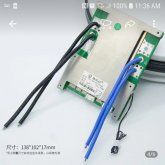
Im still going DIY individual cells, the valance was just for demonstration! Interesting point about fusing the BMS cabless, npt something ive read about before!


Im still going DIY individual cells, the valance was just for demonstration! Interesting point about fusing the BMS cabless, npt something ive read about before!
Ditto?what are you using to draw these nice diagrams
what are you using to draw these nice diagrams


My BMS has internal over current protection for the BMS sensing wires. In a large pack like my 17S 48 volt pack there is a risk of high voltage, the tradeoff of accuracy is important. A fuse will add unnecessary resistance to the sensing wires and result in incorrect voltage measurements. They do not even recommend cutting or extending the sensing wires.......IDK what the best practice is or should be for protecting the multiple smaller wires going to and from the BMS. If one or more of those wires shorts or opens (and there are 6 individual pieces of wire and 12 total connections)
Ampster beat me to it.My BMS has internal over current protection for the BMS sensing wires. In a large pack like my 17S 48 volt pack there is a risk of high voltage, the tradeoff of accuracy is important. A fuse will add unnecessary resistance to the sensing wires and result in incorrect voltage measurements. They do not even recommend cutting or extending the sensing wires.
My BMS has internal over current protection for the BMS sensing wires. In a large pack like my 17S 48 volt pack there is a risk of high voltage, the tradeoff of accuracy is important. A fuse will add unnecessary resistance to the sensing wires and result in incorrect voltage measurements. They do not even recommend cutting or extending the sensing wires.
The BMS is already controlling the current and has its own protection.
The microvolts of differential between the lines would only be complicated by adding 2 more connections per line with a fuse.
I recommend going to a bus and using a single heavier conductor simply due to the resistance of the wire..
). In either case your system isn't going to spontaneously combust or be drastically less safe either way.Yes, I understand that. My comment was in response to the OP original question about the sensing wires, but the thread has diverge to talk about the current carrying wires and your point is a good one about changing wire size and the need for over current protection for the smaller wires. I wonder how short they would need to be before being joined to a large conductor and could to be considered safe, or at least a small risk?Just to be clear, I'm not referring to the BMS sensing wires/balance leads, I'm referring to the main wires that pass current.


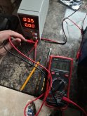
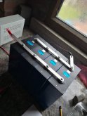
package looks greatAlrighty folks, a great update! I have just taken delivery of my battery cells. Im very impressed withcthe packaging. The batteries arenin fantastic condition andnall measuring 3.33v!
View attachment 14732View attachment 14733View attachment 14734View attachment 14735View attachment 14736View attachment 14737
Next step is to hook these up in parralel and get a top balance completes!