


You are using an out of date browser. It may not display this or other websites correctly.
You should upgrade or use an alternative browser.
You should upgrade or use an alternative browser.
LG Chem Batteries from Battery Hookup. 5.94 KWh
- Thread starter Mart Hale
- Start date
Mart Hale
New Member
- Joined
- Feb 4, 2020
- Messages
- 183
I am still happy I made the purchase. The one battery I have hooked up is running my fridge and this computer with no issues, once I get my power strip flashed with new bios I will then add more loads based upon voltage, On cloudy days I want it to do nothing but minimal loads.
I am looking forward to when the other BMS get here so I can hook up the other batteries.
I am looking forward to when the other BMS get here so I can hook up the other batteries.
Mart Hale
New Member
- Joined
- Feb 4, 2020
- Messages
- 183
At last I have finished converting this power strip by flashing the esp8266 with sonoff.bin ( Tasmota ) flash rom. Yesterday I was able to get the controls to work from Domoticz.
This video is pretty much what I did to flash this wifi power strip. I destroyed my first one, I am glad I bought two") but the second one after about 3 days of trial I figured out both what I was doing wrong with soldering, and what was wrong with the instructions for this model. It ran over night with no issues.
but the second one after about 3 days of trial I figured out both what I was doing wrong with soldering, and what was wrong with the instructions for this model. It ran over night with no issues.

Amazon.com: CRST Smart Power Strip WiFi Surge Protector Voice Control with Alexa Echo Google Home Dual USB Ports, 4 Independent APP Control Sockets, 6 Feet Extension Cord, 1875W/15A ETL Listed ¡: Home Audio & Theater
Amazon.com: CRST Smart Power Strip WiFi Surge Protector Voice Control with Alexa Echo Google Home Dual USB Ports, 4 Independent APP Control Sockets, 6 Feet Extension Cord, 1875W/15A ETL Listed ¡: Home Audio & Theater
smile.amazon.com
This video is pretty much what I did to flash this wifi power strip. I destroyed my first one, I am glad I bought two
but the second one after about 3 days of trial I figured out both what I was doing wrong with soldering, and what was wrong with the instructions for this model. It ran over night with no issues.I actually just ordered these. I believe chemistry wise these are nmc type. They also like to be under some physical pressure(clamped) . David poz did a vid on using 14 for a 48v system.Stumbled upon this yesterday: https://batteryhookup.com/products/new-lg-chem-n2-1-3-7v-120ah-cell-module
Only issue is that I cannot tell what kind of Li-ion batteries they are for DoD purposes. If any one knows please share.
Thank you!
View attachment 13131
I bought 14 but for a 24v system. I guess I could parallel 2 modules, but they already have 2 modules in parallel in each pack.
As for longevity, any good options to have a bms have a higher lower limit and a lower higher limit? The standard off the shelf bms has a very high voltage before balance begins.
bucolucas
New Member
- Joined
- Feb 28, 2020
- Messages
- 2
Just put nine of these into the battery pack for an old Ford Ranger EV:

How I managed to fit nine in the space provided

Here you can see me drilling holes for the BMS connections, with my specialized Short-Circuit Prevention Barrier

I appreciate the discussion on this thread, it helped me make the decision to buy them! There aren't any of this particular kind left. They sold a bunch of 4.75 kW modules but those sold out.
How I managed to fit nine in the space provided
Here you can see me drilling holes for the BMS connections, with my specialized Short-Circuit Prevention Barrier
I appreciate the discussion on this thread, it helped me make the decision to buy them! There aren't any of this particular kind left. They sold a bunch of 4.75 kW modules but those sold out.
Mart Hale
New Member
- Joined
- Feb 4, 2020
- Messages
- 183
I appreciate the discussion on this thread, it helped me make the decision to buy them! There aren't any of this particular kind left. They sold a bunch of 4.75 kW modules but those sold out.
I am very glad that I bought 3 of these modules... These should keep me going for several years until new tech surpasses these.
I have been thinking about what it would take to use 18650's in a Nissan leaf, I have been watching innovators in other countries making their own battery packs with lithium batteries that far surpass the batteries the cars come with. The cars are very well designed, I believe they just need to be upgraded with a new battery pack, so many of the cars are coming on the used car market and are selling for very cheap as the batteries go way down with time.
The time it would take to build 18650 into a pack is a lot more labor intensive. The larger the cells the less connections you need.I am very glad that I bought 3 of these modules... These should keep me going for several years until new tech surpasses these.
I have been thinking about what it would take to use 18650's in a Nissan leaf, I have been watching innovators in other countries making their own battery packs with lithium batteries that far surpass the batteries the cars come with. The cars are very well designed, I believe they just need to be upgraded with a new battery pack, so many of the cars are coming on the used car market and are selling for very cheap as the batteries go way down with time.
One of the LG chem battery packs is 2×60ah. That's about 500whr. Thats less than 10 cents per 1whr, or 100 bucks per kwh, virtually new.
You would need to find 18650s at a price point of less than that. If you can get them free or close to free, there is obviously some savings.
GXMnow
Solar Wizard
- Joined
- Jul 17, 2020
- Messages
- 2,792
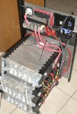
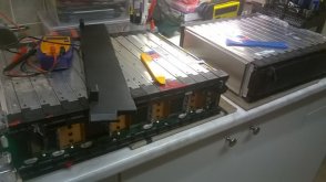
I purchased 2 of the 10S 3P and 1 of the 8S 3P LG Chem Chevy Bolt packs from Battery Hookup as the cost per KWH was hard to beat.
All of the cell groups were well within .01 volt when I got them and they do look basically new.
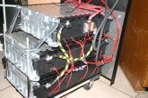
So far I made up a mounting system to hold the packs in a 19 inch equipment rack.
I cut the middle buss bar of the 8S pack to split it into two 4S sections without physically separating the pack.
I made clamp on copper terminals with matching 6mm bolts.
I used #2 cables to wire each 10S pack in series with a 4S section to make two 14S strings.
I have each 14S string connected to a buss bar with 125 amp fuses.
I purchased a JKBMS with 2 amp active balancing and common port 200 amps protection switch.
I soldered wires to each cell junction and joined the 2 strings with fuses to the single BMS.
The JKBMS seems to be working great. It allows you to customize all of the parameters. I currently have the cell over voltage set to turn off at 4.2 volts and turn back on at 4.1 volts. The cell under volt turn off is set to 3.2 and the turn on at 3.3 volts. Full turn off if any cell goes below 3.0 volts.
I have the max charge current at 145 amps. With 6 cells in parallel, that is under 25 amps per cell, or less than 0.5 C rate. The max discharge is topped out at 200 amps, which is still well below the cell capability. It also has an internal temp sensor for the the protection FET's and balance circuits and then 2 remote sensors to mount on the batteries. The battery protection temps are also fully configurable. The battery bank will live in my garage in So Cal so low temperature won't be an issue, but it can exceed 110F here. I plan to extent the temp sensors and mount them where the battery get's the hottest.
I do not have my inverter/charger yet. My current plan is to use a Schneider XW-Pro. I would set it to limit the charge voltage to just 4.1 volts per cell, and the low battery shut down will also be set to about 3.5 volts so the BMS is only a secondary safety. This should stay well away from the BMS having to step in and shut it down. I do not have any load or charger here currently that can stress these batteries. I have pumped about 600 watts in and pulled nearly 1000 watts out and the cells seem rock solid with virtually no voltage dip and they stayed at just room temp. Once my system is up and running, it will mostly be used to do self consumption. Time shifting about 10 kwh from solar production to the 5 pm to 9 pm peak TOU charge time. But I will have my Enphase solar gear and my essential loads connected after the inverter so I will also be able to run most of my home during a power failure. Doing the rough math, I should be able to keep most of my home running off grid with all the sun we get here. Just can't run that A/C compressor.
All of the cell groups were well within .01 volt when I got them and they do look basically new.
So far I made up a mounting system to hold the packs in a 19 inch equipment rack.
I cut the middle buss bar of the 8S pack to split it into two 4S sections without physically separating the pack.
I made clamp on copper terminals with matching 6mm bolts.
I used #2 cables to wire each 10S pack in series with a 4S section to make two 14S strings.
I have each 14S string connected to a buss bar with 125 amp fuses.
I purchased a JKBMS with 2 amp active balancing and common port 200 amps protection switch.
I soldered wires to each cell junction and joined the 2 strings with fuses to the single BMS.
The JKBMS seems to be working great. It allows you to customize all of the parameters. I currently have the cell over voltage set to turn off at 4.2 volts and turn back on at 4.1 volts. The cell under volt turn off is set to 3.2 and the turn on at 3.3 volts. Full turn off if any cell goes below 3.0 volts.
I have the max charge current at 145 amps. With 6 cells in parallel, that is under 25 amps per cell, or less than 0.5 C rate. The max discharge is topped out at 200 amps, which is still well below the cell capability. It also has an internal temp sensor for the the protection FET's and balance circuits and then 2 remote sensors to mount on the batteries. The battery protection temps are also fully configurable. The battery bank will live in my garage in So Cal so low temperature won't be an issue, but it can exceed 110F here. I plan to extent the temp sensors and mount them where the battery get's the hottest.
I do not have my inverter/charger yet. My current plan is to use a Schneider XW-Pro. I would set it to limit the charge voltage to just 4.1 volts per cell, and the low battery shut down will also be set to about 3.5 volts so the BMS is only a secondary safety. This should stay well away from the BMS having to step in and shut it down. I do not have any load or charger here currently that can stress these batteries. I have pumped about 600 watts in and pulled nearly 1000 watts out and the cells seem rock solid with virtually no voltage dip and they stayed at just room temp. Once my system is up and running, it will mostly be used to do self consumption. Time shifting about 10 kwh from solar production to the 5 pm to 9 pm peak TOU charge time. But I will have my Enphase solar gear and my essential loads connected after the inverter so I will also be able to run most of my home during a power failure. Doing the rough math, I should be able to keep most of my home running off grid with all the sun we get here. Just can't run that A/C compressor.
Attachments
Mart Hale
New Member
- Joined
- Feb 4, 2020
- Messages
- 183
I purchased 2 of the 10S 3P and 1 of the 8S 3P LG Chem Chevy Bolt packs from Battery Hookup as the cost per KWH was hard to beat.
All of the cell groups were well within .01 volt when I got them and they do look basically new.
So far I made up a mounting system to hold the packs in a 19 inch equipment rack.
I cut the middle buss bar of the 8S pack to split it into two 4S sections without physically separating the pack.
I made clamp on copper terminals with matching 6mm bolts.
I used #2 cables to wire each 10S pack in series with a 4S section to make two 14S strings.
I have each 14S string connected to a buss bar with 125 amp fuses.
I purchased a JKBMS with 2 amp active balancing and common port 200 amps protection switch.
I soldered wires to each cell junction and joined the 2 strings with fuses to the single BMS.
The JKBMS seems to be working great. It allows you to customize all of the parameters. I currently have the cell over voltage set to turn off at 4.2 volts and turn back on at 4.1 volts. The cell under volt turn off is set to 3.2 and the turn on at 3.3 volts. Full turn off if any cell goes below 3.0 volts.
I have the max charge current at 145 amps. With 6 cells in parallel, that is under 25 amps per cell, or less than 0.5 C rate. The max discharge is topped out at 200 amps, which is still well below the cell capability. It also has an internal temp sensor for the the protection FET's and balance circuits and then 2 remote sensors to mount on the batteries. The battery protection temps are also fully configurable. The battery bank will live in my garage in So Cal so low temperature won't be an issue, but it can exceed 110F here. I plan to extent the temp sensors and mount them where the battery get's the hottest.
I do not have my inverter/charger yet. My current plan is to use a Schneider XW-Pro. I would set it to limit the charge voltage to just 4.1 volts per cell, and the low battery shut down will also be set to about 3.5 volts so the BMS is only a secondary safety. This should stay well away from the BMS having to step in and shut it down. I do not have any load or charger here currently that can stress these batteries. I have pumped about 600 watts in and pulled nearly 1000 watts out and the cells seem rock solid with virtually no voltage dip and they stayed at just room temp. Once my system is up and running, it will mostly be used to do self consumption. Time shifting about 10 kwh from solar production to the 5 pm to 9 pm peak TOU charge time. But I will have my Enphase solar gear and my essential loads connected after the inverter so I will also be able to run most of my home during a power failure. Doing the rough math, I should be able to keep most of my home running off grid with all the sun we get here. Just can't run that A/C compressor.
GXMnow
Solar Wizard
- Joined
- Jul 17, 2020
- Messages
- 2,792
Here is the page from Ali Express
 www.aliexpress.com
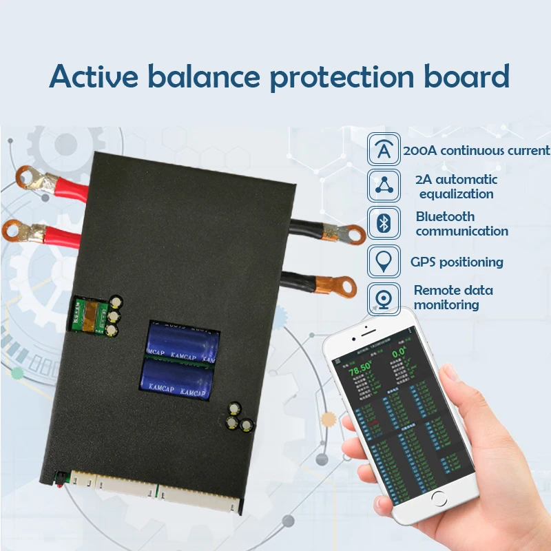
Several vendors carry the same boards. This one had fairly quick free delivery. They were also very responsive to messages.
The casing has changed and the caps are now enclosed in the cast housing. They did not have the 200 amp in stock and it had to be built, so it took over 2 weeks before it shipped. Once it did ship, I had it in 4 days.
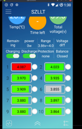
The setup is quite easy, but there are two things that had me confused at first. Once I got it all connected, it would not turn on and just sat there. It turns out you need to supply a charging current that will push about 5 volts higher than the battery voltage. My test pack was near full charge and so the difference with a CC/CV charger was only 1 volt. I had to use a separate power supply to get it to wake up. The next thing I figured out was that once you make a setup change, like the number of cells, you have to do a full shut down and power it up again with the over 5 volt kick again. Once it is in my solar bank, this should not be a problem, but it was a bit confusing with the poor instructions. The 200 amp version has 2 amps of balance current. It is a true active energy balance system. On the app, you can watch it pull 2 amps from the cell with the highest voltage, and then push 2 amps into the cell with the lowest voltage. The two large caps are actually 35 farad super caps to hold the energy it is moving. My pack was already pretty close to balanced, so it only cycled for about an hour and now all 14 cell groups are within 0.003 volts so the balancing section is basically shut down. If any cell goes more than 0.005 out of balance it will start up again. You can also set the balance threshold as well as reduce the balance current if 2 amps is too much.
The one concern I do have is the cables are just two #7 AWG. That seems a bit light for a 200 amp rating. The charge current from the Schneider XW can hit 140 amps, and at full constant load, it could draw 140 amps, and surge to well over 200. I do not plan to run it that hard, but I don't want 4 inches of wire to be the limiter.
14.61US $ 13% OFF|1a/2a Acactive Bms Li-ion Lifepo4 Battery 13s-24s Balancer Protection Board Bluetooth-compatible Can/rs485 Communication - Battery Accessories & Charger Accessories - AliExpress
Smarter Shopping, Better Living! Aliexpress.com
Several vendors carry the same boards. This one had fairly quick free delivery. They were also very responsive to messages.
The casing has changed and the caps are now enclosed in the cast housing. They did not have the 200 amp in stock and it had to be built, so it took over 2 weeks before it shipped. Once it did ship, I had it in 4 days.
The setup is quite easy, but there are two things that had me confused at first. Once I got it all connected, it would not turn on and just sat there. It turns out you need to supply a charging current that will push about 5 volts higher than the battery voltage. My test pack was near full charge and so the difference with a CC/CV charger was only 1 volt. I had to use a separate power supply to get it to wake up. The next thing I figured out was that once you make a setup change, like the number of cells, you have to do a full shut down and power it up again with the over 5 volt kick again. Once it is in my solar bank, this should not be a problem, but it was a bit confusing with the poor instructions. The 200 amp version has 2 amps of balance current. It is a true active energy balance system. On the app, you can watch it pull 2 amps from the cell with the highest voltage, and then push 2 amps into the cell with the lowest voltage. The two large caps are actually 35 farad super caps to hold the energy it is moving. My pack was already pretty close to balanced, so it only cycled for about an hour and now all 14 cell groups are within 0.003 volts so the balancing section is basically shut down. If any cell goes more than 0.005 out of balance it will start up again. You can also set the balance threshold as well as reduce the balance current if 2 amps is too much.
The one concern I do have is the cables are just two #7 AWG. That seems a bit light for a 200 amp rating. The charge current from the Schneider XW can hit 140 amps, and at full constant load, it could draw 140 amps, and surge to well over 200. I do not plan to run it that hard, but I don't want 4 inches of wire to be the limiter.
GXMnow
Solar Wizard
- Joined
- Jul 17, 2020
- Messages
- 2,792
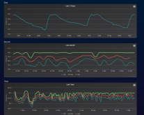
As I have been closely monitoring my LG Bolt batteries, I decided to make a few measurements. I am not stressing them at all yet. All of these values are being taken from the Schneider XW-Pro battery summary graphs, and the measured volts are inside the inverter, so all losses are included.
I am charging at under 26 amps and discharging at under 33 amps. This is all less than 0.1C on my total 360 amp hour pack. When the batteries go from resting for an hour to discharging at 28.3 amps, the battery dropped from 57.47 volts, to 57.17 volts. So a drop of 0.3 volts at 28.3 amps = 10.6 milliohms. But remember, this is at the inverter input. So it goes from 14 cells in series, then through two 125 amp fuses in parallel, then the BMS and shut off switch, and 8 feet + 8 feet of 2/0 cable. I already calculated the BMS as being about 1 milliohm, and the wire is a fair share of this loss also. I even saw about 6 mv drop on the jumper cable between the 10S and 4S packs. So I am pretty happy with this value. I will try and measure just the voltage at the terminals of the 10S pack when I cycle the current on and off. On the charge side, with the battery bank at about 50% charge, I got a similar result. The current went from zero to 25.96, and the voltage went from 50.61 to 50.81 which calculates out to 7.7 milliohms all the way to the inverter again. I have done 50% capacity cycles for 5 days now, and everything looks great. I have not pulled the pack below 50 volts yet so still above 3.57 volts per cell. but at these cycles and the low current level, everything is staying cool. My wiring into the panel is still temp. The most current I could pull would only be in the 70 amp range, still just 0.2 C.
It is times like this I realize how much power that little pack can really put out.
Mart Hale
New Member
- Joined
- Feb 4, 2020
- Messages
- 183
Well after about 2 weeks I now have all 3 batteries online so 16 KWH of storage ( of which I use maybe 14 KWH as I am only charging up to 4.0 V so that I can prolong the life of these packs. I have been dropping over 2700 Watts of power via solar to them, and they have been responding very well. Solar system dumps from 6 - 10 KWH a day into them. This has been tons of fun to see power real power there when I need it.
GXMnow
Solar Wizard
- Joined
- Jul 17, 2020
- Messages
- 2,792
My bank is still working great. They have been charging to 4.1 volts per cell, and then discharging to 3.6 volts per cell for several month now with no issues at all. My BMS reports 97% full down to 50% with those voltages. I did lower my full charge voltage to 57 volts (4.07 per cell) which works out to about 85% charge with the Chevy recall announcement. They are telling owners of the Chevy Bolt which these cells come from to not charge over the 90% capacity setting. At 4.0 you are well under that. I am pushing about 8 KWH in and back out each day. I have 2 strings of 14S3P.
GXMnow
Solar Wizard
- Joined
- Jul 17, 2020
- Messages
- 2,792
From all I can find, it was modules built in South Korea and sold in North American Chevy Bolts. There is no recall in other countries at this time. My modules are marked LG Chem Vista 2.0 made in South Korea. Only charging to 57 volts on 14S is working fine for me. They run stone cold. Have not seen or felt them ever any different temp than the metal cabinet in my garage. While on grid without my A/C running in the cool weather, I am able to fully power my home through the 5 hours of peak energy rate and still have nearly 50% battery left.
Mart Hale
New Member
- Joined
- Feb 4, 2020
- Messages
- 183
At last! I finally got the right connector after 4 times of odering ( my error for not understanding the different types of JST connectors ) but my bluetooth BMS is only. I am glad I got this now I can check battery voltages without fighting with voltage meter.
Attachments
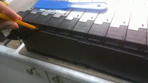
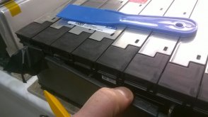
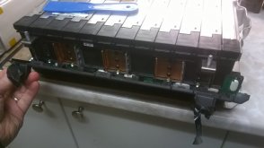
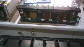
Andrew, The side panels pop out you have to release each tab slowly before they come off.
Thanks Mart for this tip. I realize I am way late here, but I had trouble with this initially, too, and so am posting some pics to supplement Mart's answer in case that's helpful to anyone else.I bought one of these modules as well, how easy was it to clip off the side panels to show the connections? I tried unclipping mine and it’s giving a lot of resistance, I don’t want to snap them off completely.
Attachments
Late to the thread, can you share you experience with this inverter pls?36V inverter has arrived. Testing one of these bad boys out now.
Branks, $$, performance.
Thanksl
Hi GXMnow,I purchased 2 of the 10S 3P and 1 of the 8S 3P LG Chem Chevy Bolt packs from Battery Hookup as the cost per KWH was hard to beat.
All of the cell groups were well within .01 volt when I got them and they do look basically new.
So far I made up a mounting system to hold the packs in a 19 inch equipment rack.
I cut the middle buss bar of the 8S pack to split it into two 4S sections without physically separating the pack.
I made clamp on copper terminals with matching 6mm bolts.
I used #2 cables to wire each 10S pack in series with a 4S section to make two 14S strings.
I have each 14S string connected to a buss bar with 125 amp fuses.
I purchased a JKBMS with 2 amp active balancing and common port 200 amps protection switch.
I soldered wires to each cell junction and joined the 2 strings with fuses to the single BMS.
The JKBMS seems to be working great. It allows you to customize all of the parameters. I currently have the cell over voltage set to turn off at 4.2 volts and turn back on at 4.1 volts. The cell under volt turn off is set to 3.2 and the turn on at 3.3 volts. Full turn off if any cell goes below 3.0 volts.
I have the max charge current at 145 amps. With 6 cells in parallel, that is under 25 amps per cell, or less than 0.5 C rate. The max discharge is topped out at 200 amps, which is still well below the cell capability. It also has an internal temp sensor for the the protection FET's and balance circuits and then 2 remote sensors to mount on the batteries. The battery protection temps are also fully configurable. The battery bank will live in my garage in So Cal so low temperature won't be an issue, but it can exceed 110F here. I plan to extent the temp sensors and mount them where the battery get's the hottest.
I do not have my inverter/charger yet. My current plan is to use a Schneider XW-Pro. I would set it to limit the charge voltage to just 4.1 volts per cell, and the low battery shut down will also be set to about 3.5 volts so the BMS is only a secondary safety. This should stay well away from the BMS having to step in and shut it down. I do not have any load or charger here currently that can stress these batteries. I have pumped about 600 watts in and pulled nearly 1000 watts out and the cells seem rock solid with virtually no voltage dip and they stayed at just room temp. Once my system is up and running, it will mostly be used to do self consumption. Time shifting about 10 kwh from solar production to the 5 pm to 9 pm peak TOU charge time. But I will have my Enphase solar gear and my essential loads connected after the inverter so I will also be able to run most of my home during a power failure. Doing the rough math, I should be able to keep most of my home running off grid with all the sun we get here. Just can't run that A/C compressor.
Your set up sounds great. One question for you: you say you're planning to install the Schneider XW-Pro. I am designing my system now and am looking at the Outback Radian compared to the Schneider. I have a really similar battery set-up and am wondering if you compared the Radian and Schneider and prefer the Schneider. I'm leaning toward the Radian but am interested to know if I missed anything in my research and maybe am better to go with Schneider . . . Thanks!
Mart Hale
New Member
- Joined
- Feb 4, 2020
- Messages
- 183
Sure thing, I am very pleased with this inverter. It has been running for months supplying power to my PC, frig, instant pot, bread machine, and several lights. About a month ago I pushed it too hard when combining both my microwave (1200 watts) combined with well pump ( pulls 800 watts ) and blew the auto fuse on one of the circuits. I replaced it and I was right back in business ( they send extras) Since that point I moved the heavier loads to my 24 V system and that has taken care of my problems, I use heave loads like table saw, and microwave on the 24V system, and my constant loads like frig I use this 36 V inverter. I recommend when ever using a Chinese inverter only using 2/3 of it's rated watts, and not for heavy lifting. It did run the microwave by itself, but I don't want to put any stress on the inverter more, I have gone as far as I am willing to experiment with.Late to the thread, can you share you experience with this inverter pls?
Branks, $$, performance.
Thanksl
Attachments
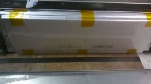
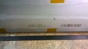
Hi there, I'm writing to see if anyone has figured out the pin-out on the 5.94 kwH module or the 4.75 kwH Module. I'll post some pics here of the connector (8-pin female) and of the modules I've got just to be sure that I'm being clear about the connector I mean - I read through another thread on another forum, https://secondlifestorage.com/index.php?threads/w0ss-semi-diy-powerwall-v2.8454/, but believe that the pin-out that Woss posted there is for a different module (pls. correct me if I'm wrong, though). Thanks for any help!
Attachments
![WP_20210315_15_32_08_Pro[1].jpg](/data/attachments/41/41096-bc8d7c92afca5c7ee528902013304007.jpg)
![WP_20210315_15_00_51_Pro[1].jpg](/data/attachments/41/41097-3b516d2008083439373890996e291403.jpg)
Mart Hale
New Member
- Joined
- Feb 4, 2020
- Messages
- 183
I have not but a word of warning....Hi there, I'm writing to see if anyone has figured out the pin-out on the 5.94 kwH module or the 4.75 kwH Module. I'll post some pics here of the connector (8-pin female) and of the modules I've got just to be sure that I'm being clear about the connector I mean - I read through another thread on another forum 'secondlifestorage,' but believe that the pin-out that Woss posted there is for a different module (pls. correct me if I'm wrong, though). Thanks for any help!
Positive and Negative are not always on the same side of the battery. 2 dead BMS's later I figured it out, just verify positive and negative.
What I did was drill each tab on side of the battery and used small bolts to secure the connections, I tried soldering, but that was a fruitless venture for me, the bolts worked awesome.
Similar threads
- Replies
- 4
- Views
- 1K
- Replies
- 5
- Views
- 1K
- Replies
- 1
- Views
- 949
- Replies
- 7
- Views
- 988