Thanks @uksa007.The Heat+CAN mode has Heat output and CAN(not used as it is proprietary JK protocol)
Both will work, if you need the heat function get the Heat version if not, get the non Heat version.
You are using an out of date browser. It may not display this or other websites correctly.
You should upgrade or use an alternative browser.
You should upgrade or use an alternative browser.
JK BMS CAN bus comms now possible for inverters that support Goodwe and Pylontech batteries
- Thread starter uksa007
- Start date
Sleeper85
Sunday handyman
- Joined
- Nov 28, 2022
- Messages
- 443
V1.15.5 on GitHub
I decided to deactivate the API reboot every 15 minutes if there is no connection with HA, I think we should prevent the ESP32 from rebooting which could happen during a Bulk charge. I also adapted the default discharge current to 120A therefore 6000W.
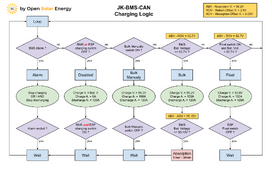
In addition, as I received a lot of questions regarding the operation of the charging logic I created the diagram below to make it clear.

Last edited:
arzaman
New Member
- Joined
- Nov 9, 2022
- Messages
- 42
I'd like to share a neat and simple hardware alternative for implementing the protocol converter.
I utilized components from M5stack
ATOM Lite, an ESP32 pico controller
ATOMIC CANBus Base (based on CA-IS3050G transceiver)
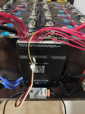
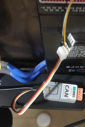
By simply connecting the 'grove' port to the JK-BMS TTL GPS port with a straightforward JST cable adapter and routing the CAN output to the Deye sun-5k-sg03lp1-eu inverter, everything functions seamlessly, as demonstrated.
The power supply is currently temporary from the USB-C Atom port.
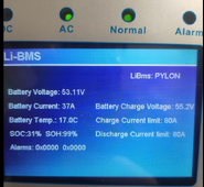
My next steps involve integrating a DC-DC step-down converter to power the circuit (and possibly my Rpi running home assistant) from Vbat. Additionally, I plan on incorporating an OLED display to visualize real-time relevant parameters like State of Charge (SoC) and voltage.
enjoy
Davide
I utilized components from M5stack
ATOM Lite, an ESP32 pico controller
ATOMIC CANBus Base (based on CA-IS3050G transceiver)

By simply connecting the 'grove' port to the JK-BMS TTL GPS port with a straightforward JST cable adapter and routing the CAN output to the Deye sun-5k-sg03lp1-eu inverter, everything functions seamlessly, as demonstrated.
The power supply is currently temporary from the USB-C Atom port.

My next steps involve integrating a DC-DC step-down converter to power the circuit (and possibly my Rpi running home assistant) from Vbat. Additionally, I plan on incorporating an OLED display to visualize real-time relevant parameters like State of Charge (SoC) and voltage.
enjoy
Davide
What software is running on the controller? Do you have a complete build sheet/instructions?I'd like to share a neat and simple hardware alternative for implementing the protocol converter.
I utilized components from M5stack
ATOM Lite, an ESP32 pico controller
ATOMIC CANBus Base (based on CA-IS3050G transceiver)
View attachment 187756
By simply connecting the 'grove' port to the JK-BMS TTL GPS port with a straightforward JST cable adapter and routing the CAN output to the Deye sun-5k-sg03lp1-eu inverter, everything functions seamlessly, as demonstrated.
The power supply is currently temporary from the USB-C Atom port.
View attachment 187757
My next steps involve integrating a DC-DC step-down converter to power the circuit (and possibly my Rpi running home assistant) from Vbat. Additionally, I plan on incorporating an OLED display to visualize real-time relevant parameters like State of Charge (SoC) and voltage.
enjoy
Davide
arzaman
New Member
- Joined
- Nov 9, 2022
- Messages
- 42
What software is running on the controller? Do you have a complete build sheet/instructions?
the one kindly supported and maintained open source by @Sleeper85 in his repo (great thanks)
GitHub - Sleeper85/esphome-jk-bms-can
Contribute to Sleeper85/esphome-jk-bms-can development by creating an account on GitHub.
Sleeper85
Sunday handyman
- Joined
- Nov 28, 2022
- Messages
- 443
What software is running on the controller? Do you have a complete build sheet/instructions?
He adapted the YAML available on GitHub for the ESP32 pico.
CAN board base (Atom CAN)
ESP32 pico board (Atom Lite)
Just buy these two components and put them together like Lego.
I could add a YAML dedicated to this solution for those who are interested.
You can purchase both components as a kit.
M5Stack Official Store (Aliexpress)
Last edited:
arzaman
New Member
- Joined
- Nov 9, 2022
- Messages
- 42
He adapted the YAML available on GitHub for the ESP32 pico.
CAN board base (Atom CAN)
ESP32 pico board (Atom Lite)
Just buy these two components and put them together like Lego.
I could add a YAML dedicated to this solution for those who are interested.
You can purchase both components as a kit.
Exactly !
I just edit few parameters in the original yaml file
here are the modifications
Code:
# GPIO pins your CAN bus transceiver ATOMIC CANBus Base (CA-IS3050G)
  can_tx_pin: GPIO22
  can_rx_pin: GPIO19
# GPIO pins your JK-BMS RS485(TTL) is connected to the grove port of ATOM lite
  tx_pin: GPIO32
  rx_pin: GPIO26

  esp32:
  board: m5stack-atom
  framework:
    type: arduino
on top of this due to my config
I enable Home Assistant API
I fixed IP address on ESP32
Cable connection between RS232 TTL JK port and M5stack Atom port is very simple just GND, TX, RX
Thanks. And this replaces that 'other' expensive board for the JK and then can interface with many inverters? Assume there is no ability to chain these together for multiple packs?He adapted the YAML available on GitHub for the ESP32 pico.
CAN board base (Atom CAN)
ESP32 pico board (Atom Lite)
Just buy these two components and put them together like Lego.
I could add a YAML dedicated to this solution for those who are interested.
You can purchase both components as a kit.
M5Stack Official Store (Aliexpress)
Last edited:
arzaman
New Member
- Joined
- Nov 9, 2022
- Messages
- 42
Thanks. And this replaces that 'other' expensive board for the JK and then can interface with many inverters?
If you have only one battery bank and inverter, I would definitely say yes!
here screenshot of my Deye inverter configured as "Pylon"
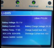
I followed the instructions to compile it on EspHome, connected the two cables, and it's working perfectly (along with Home Assistant monitoring).
The only 'limitation' is that to power the M5stack Atom, you currently need to connect a USB-C cable to a 5V power supply. I'm in the process of developing a simple DC-DC converter PCB to directly draw 5V from the Vbat of the JK-BMS port. This way, it will become a plug-and-play autonomous solution
Thank you!!! Assume only one JK/Battery pack though. Can't combine/monitor multiple?If you have only one battery bank and inverter, I would definitely say yes!
here screenshot of my Deye inverter configured as "Pylon"
View attachment 187795
I followed the instructions to compile it on EspHome, connected the two cables, and it's working perfectly (along with Home Assistant monitoring).
The only 'limitation' is that to power the M5stack Atom, you currently need to connect a USB-C cable to a 5V power supply. I'm in the process of developing a simple DC-DC converter PCB to directly draw 5V from the Vbat of the JK-BMS port. This way, it will become a plug-and-play autonomous solution
Also great work @Sleeper85 and @arzaman !!!
Sleeper85
Sunday handyman
- Joined
- Nov 28, 2022
- Messages
- 443
Can't buy the kit, marked EOL but These seem to be the correct parts, correct?
View attachment 187799
Yes
Sleeper85
Sunday handyman
- Joined
- Nov 28, 2022
- Messages
- 443
Thank you!!! Assume only one JK/Battery pack though. Can't combine/monitor multiple?
Also great work @Sleeper85 and @arzaman !!!
No, this YAML only supports a single BMS connection and I have not planned a multi-BMS version.
Other solutions are the Uksa007 boards or the new JK-BMS for inverter.
Regarding the new JK-BMS for inverter, the memory loss problem is fixed with the latest version V14.17.
Info coming from Andy.
arzaman
New Member
- Joined
- Nov 9, 2022
- Messages
- 42
Can't buy the kit, marked EOL but These seem to be the correct parts, correct?
View attachment 187799
Suggesto also to add some accessories to make the connections easy (are not included with Atome and Base)
Short "grove" patch cable (4 pin)
Grove to PIN adatper where you can connect/solder the JST cable from JK BMS

Thank you. Have everything in my cart. Looks to be a max of 60 days shipping to U.S.Suggesto also to add some accessories to make the connections easy (are not included with Atome and Base)
Short "grove" patch cable (4 pin)
Grove to PIN adatper where you can connect/solder the JST cable from JK BMS
View attachment 187800
View attachment 187801
You could also use a Seplos V3 which I believe Andy recommends now, just need to add an active balancer if needed.Regarding the new JK-BMS for inverter, the memory loss problem is fixed with the latest version V14.17.
arzaman
New Member
- Joined
- Nov 9, 2022
- Messages
- 42
Try some global (Digikey, Mouser) distributor or local oneThank you. Have everything in my cart. Looks to be a max of 60 days shipping to U.S.
M5Stack - Modular Rapid ESP32 IoT Development Board - ESP32 dev kits
Open-source modular toolkits for IoT devices based on ESP32-updated version of ESP8266. With stackable modules, user-friendly IDE, enabling rapid and high-quality prototyping, STEM education, engineering and mechanical use.
@arzaman Thanks, I can get all pretty quickly except for the 4-pin connector. Guess I can just wire directly/solder from the JK to the unbuckled wire. What type of connector is needed on the JK BMS itself?Try some global (Digikey, Mouser) distributor or local one
M5Stack - Modular Rapid ESP32 IoT Development Board - ESP32 dev kits
Open-source modular toolkits for IoT devices based on ESP32-updated version of ESP8266. With stackable modules, user-friendly IDE, enabling rapid and high-quality prototyping, STEM education, engineering and mechanical use.m5stack.com
Sleeper85
Sunday handyman
- Joined
- Nov 28, 2022
- Messages
- 443
@arzaman Thanks, I can get all pretty quickly except for the 4-pin connector. Guess I can just wire directly/solder from the JK to the unbuckled wire. What type of connector is needed on the JK BMS itself?
As written in the readme, JST 1.25mm pitch.
Code:
# RS485-TTL jack on JK-BMS (4 Pin, JST 1.25mm pitch)
┌─── ─────── ────┐
│                │
│ O   O   O   O  │
│GND  RX  TX VBAT│
└────────────────┘
  │   │   │   | VBAT is full battery volatge eg 51.2V (No connect)
  │   │   └──── ESP32 GPIO16 (`rx_pin`)
  │   └──────── ESP32 GPIO17 (`tx_pin`)
└──────────── GNDSimilar threads
- Replies
- 1K
- Views
- 28K
- Replies
- 46
- Views
- 8K
- Replies
- 2
- Views
- 329
- Replies
- 9
- Views
- 471
- Replies
- 38
- Views
- 3K


