diy solar

diy solar

99.5% Efficient Inverter Design

Low voltage rated mosfets win hands down when run at low voltages.
The "on" resistance is so very low, nothing else even comes close for conduction losses and speed.

But as the voltage rating of the mosfet increases, the "on" resistance rises much faster. High voltage mosfets are pretty miserable devices.

As RC above ^^ says, these days anything that runs over about 100v to 150v that also must run at reasonably high power, will likely be an IGBT.
Over the last ten years or so, IGBTs have massively improved in both speed and conduction losses.

You will find that all the high voltage grid tie inverters run IGBTs, never mosfets.
There is still a place for mosfets in an off grid inverter running at 48v, they are still by far the best choice for high frequency pwm at lower voltages.

These big IGBT power bricks are very slow, especially the older ones, and quite unsuitable for high frequency pwm, except in variable frequency drives where the pwm might be only a very few Khz or even hundreds of Hz. But they are perfect for switching very high power at 50/60Hz.

There is also another aspect of this that nobody talks about. These big devices may be rated for hundreds of amps, and the voltage drop across the IGBT might be a couple of volts, which is really too high for a low voltage inverter. But at much lower power, say ten or twenty amps, the voltage drop is actually quite low. Not as low as a low voltage mosfet, but acceptably low for an off grid inverter.

After building this monster and running it at 100v dc over four years, I would have no hesitation building another one to run at 48v using the exact same IGBTs.
With average mixed continuous domestic loads, which are mostly below 1Kw, the inverter efficiency is really quite good, even with IGBTs.

For really high power, a hundred dc amps is probably the practical maximum, say 5Kw at 48v. If you go up to 100v its only fifty amps and the losses from voltage drops around the system will be far lower. The only practical difficulty with high dc voltage becomes the large number of battery cells to maintain. But on the whole, I am very happy how my 100v system has worked out.
 
Peripheral topic mentioned in this thread: How does an inverter deal with a not perfect power factor? In a low frequency with an H-bridge it makes sense that the current would end up moving in and out of the battery with the net being current flowing out of the battery. What happens in high frequency inverters?
 
Peripheral topic mentioned in this thread: How does an inverter deal with a not perfect power factor? In a low frequency with an H-bridge it makes sense that the current would end up moving in and out of the battery with the net being current flowing out of the battery. What happens in high frequency inverters?
For reactive power factor, like an inductive motor, during a portion of the AC cycle the current goes in reverse.

A LF inverter will actually have reverse current to battery during a portion of cycle.

A HF inverter will just push the AC reverse current to the HV DC filter capacitor. The battery to HV DC converter will just shut down, or significantly reduce its output, when HV DC filter capacitor rises in voltage due to momentary back feed. There is a limit to how poor the power factor can be as it can overvoltage the HV filter capacitor. This action also drives the converter regulating feedback control crazy and can result in battery to HV DC converter instability.

This is why HF inverters do not handle poor power factor loads well.

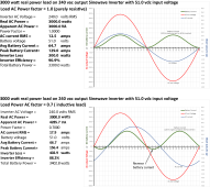
Waveform below is for a LF inverter. Notice the battery ripple current is twice the AC line output frequency.

Inverter power factor waveform.png
 
Last edited:
For reactive power factor, like an inductive motor, during a portion of the AC cycle the current goes in reverse.

A LF inverter will actually have reverse current to battery during a portion of cycle.

A HF inverter will just push the AC reverse current to the HV DC filter capacitor. The battery to HV DC converter will just shut down, or significantly reduce its output, when HV DC filter capacitor rises in voltage due to momentary back feed. There is a limit to how poor the power factor can be as it can overvoltage the HV filter capacitor. This action also drives the converter regulating feedback control crazy and can result in battery to HV DC converter instability.

This is why HF inverters do not handle poor power factor loads well.

A HF inverter can handle LPF loads fine if it is bi-directional. Most of the typical HF inverter/chargers may not do it this way.

An example of bi-directional HF inverters would be the new MidNite Solar B17 and Rosie inverters and also the Sol-Ark (I think)

boB
 
Last edited:
It depends on the type of HF inverter topology , exactly as you say.

Some (all ?) of the cheap Chinese HF inverters use a flyback transformer which is NOT bidirectional. To make it worse the electrolytics on the high voltage dc bus may also be barely adequate, and highly reactive loads will probably be a death sentence for the inverter.

Better engineered and higher quality HF inverters will use forward converters which ARE bi directional, and that goes towards making it a bit more robust for nasty loads.

But really the ultimate will be a transformer pwm inverter that does all the voltage increasing in a large heavy 50/60Hz transformer. That will handle both high surge loads and reactive loads far better.
 
I used to have a Growatt 12000t (low frequency), when I was testing it initially I would have odd problems with a BMS on a 100AH NMC 14S battery, and I ended up figuring out that the PF from my AC compressor was going back through and causing jitter in the voltage readings - which caused me to learn about replacing the caps every year.

I have a transformer I got a good deal on a while back - a 25KVA 480x240-240/120 with a bunch of taps, that I eventually wanted to use it to generate NA neutral with these and AC couple with a second tier of second-life batteries away from my house.

I’m hacking on my own program to communicate with JK balancers to make my own sort of BMS which I could cascade the balancers to whatever series of cells I needed.

It occurred to me reading through this thread that it could be a real interesting project to match a higher voltage DC battery with an H-bridge and this transformer.
 
Maybe,
But one thing to check before you do anything.
Connect it up to the grid (through one of the windings) and measure the idling power.
Some of those large transformers have a horrendously high magnetizing current, and will bleed your battery white, even without any additional load.
What is too much, is entirely up to you.
 
It depends on the type of HF inverter topology , exactly as you say.

Some (all ?) of the cheap Chinese HF inverters use a flyback transformer which is NOT bidirectional. To make it worse the electrolytics on the high voltage dc bus may also be barely adequate, and highly reactive loads will probably be a death sentence for the inverter.
oh no it’s a smoke
 
Hi Warpspeed, i trust you are well?

Honest to gould, ...... folk build our stuff. then they blow it up with tinkering on a working Ozinverter.

The latest is teenagers of families, opening the cabinet door and pressing the control board Re-set button on the PWM 8010 chip and while the inverter is ruddy running.

Sometimes i despair at what supposedly intelligent human beings actually do.

I will build in a little circuit that does not allow the Reset to happen when the Inverter main On switch is depressed.
Reset.... 'Oztules' and I found that sometimes the 8010 PWM might just hang, possible reasons yes, but sorting it out means more complications.

Lots of capital projects on at present, but i have started working on the new modern D.I.Y. PLANTE lead acid batteries again. They are looking good.
 
Hello Leslie, good to hear from you again.
The 8010 is now known to have a bit of a "personality".
The internal software that makes it go sometimes has a Joe Biden moment.
The guys at the Back Shed Forum have come up with some alternatives using a Nono microthingy that might be of interest.

I bet its warmer where you are right now, we have just had our winter solstice down here, and its cold wet and sky is grey.
 
A HF inverter can handle LPF loads fine if it is bi-directional. Most of the typical HF inverter/chargers may not do it this way.

An example of bi-directional HF inverters would be the new MidNite Solar B17 and Rosie inverters and also the Sol-Ark (I think)

boB
Most high freq all-in-one inverters do not have a true bi-directional battery to HV DC converter. They switch modes by placing a buck switcher IGBT or MOSFET in HV DC inductor path. Some HF inverters use a mechanical relay switch across this device when in normal forward power mode to avoid device resistance loss of the extra series device that would reduce forward inverter battery to AC out efficiency of inverter.

Because there is some mode change over time this prevents many HF AIO inverters from doing AC load shaving. They cannot switch mode between charging battery and supplying inverter AC load supplementing fast enough.

It is difficult to design and reliably control a true high power, high efficiency, bi-directional battery to HV DC converter.

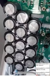
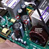
SolArk and Deye uses a large bank of high voltage DC filter capacitors to give storage margin to make the mode switchover on converter giving the appearance of a true bi-directional converter. SolArk has about 15x the amount of HV DC filter capacitance compared to other HF inverters like MPP Solar.
Deye inverter HV caps(14x 1000 uF)-------MPP Solar 5 kVA inverter HV caps (2x 470 uF)
Deye HV DC filter.jpg MPP PIP5048 board HV caps.jpg

A low freq inverter is inherently bi-directional. Does not even need immediate PWM controller adjustment intervention. They are like a manual transmission auto when you take your foot off of accelerator pedal. Forward momentum energy is pushed back into engine. Also like regenerative breaking used in EV's.
 
Last edited:
I’m just learning some more practical electronics, although I have a Math background and read through some EE theory books.

My novice approach to a bi-directional HF inverter would be to essentially have two separate parts. One would ignorantly generate the base frequency, and the other would act like a load matching the impedance of other sources over the base frequency, and shuffle that energy back into the battery (or some in-between to smooth out current in/out of battery).

Are those caps in the Deye for the HVDC internal bus? So the DC/DC converter between the battery and the bus can change direction according to the net flow, like you indicated?
 
Most high freq all-in-one inverters do not have a true bi-directional battery to HV DC converter. They switch modes by placing a buck switcher IGBT or MOSFET in HV DC inductor path. Some HF inverters use a mechanical relay switch across this device when in normal forward power mode to avoid device resistance loss of the extra series device that would reduce forward inverter battery to AC out efficiency of inverter.

Because there is some mode change over time this prevents many HF AIO inverters from doing AC load shaving. They cannot switch mode between charging battery and supplying inverter AC load supplementing fast enough.

It is difficult to design and reliably control a true high power, high efficiency, bi-directional battery to HV DC converter.

SolArk and Deye uses a large bank of high voltage DC filter capacitors to give storage margin to make the mode switchover on converter giving the appearance of a true bi-directional converter. SolArk has about 15x the amount of HV DC filter capacitance compared to other HF inverters like MPP Solar.
Deye inverter HV caps----------------------MPP Solar 5 kVA inverter HV caps
View attachment 100588 View attachment 100592

A low freq inverter is inherently bi-directional. Does not even need immediate PWM controller adjustment intervention. They are like a manual transmission auto when you take your foot off of accelerator pedal. Forward momentum energy is pushed back into engine. Also like regenerative breaking used in EV's.

RC, I have looked at both of these inverters and agree totally about the MPP Solar and other Asian HF inverter/chargers that they use two parallel back-to-back converters.
Looking at the Sol-Ark, it appeared to me that they used IGBTs as synchronous rectifiers and so I thought it was bi-directional.

Why does the Sol-Ark/Deye use 3 transformers though ? I did not get that far.

Also, in general for others, when we say "low frequency inverter", we really mean low frequency 50Hz/60Hz transformer but high frequency switching on the primary side.

boB
Just about all the HF AIO use synchronous IGBT rectifier H-bridge, HF phase synchronous to battery side HF transformer battery side input MOSFET switching.

The HV DC nodes (two separate HV DC nodes for each 120 vac phase) run at about 250 vdc. The HV filter caps in SolArc/Deye have 315 vdc voltage rating. HF split phase inverters are essentially two 120vac inverters stacked in series. Each inverter supplying half of inverter power rating. Same thing goes for 240/120vac split phase inverter-generators.

The issue is how to distribute common PV SCC power to two isolated HV DC nodes.
The third HF transformer is likely for PV SCC output to isolate and lower the SCC modules DC output voltage since the max PV input can be 500vdc. The SCC's boosts input PV Vmp voltage up to 500 vdc then there is a high efficiency forward HF DC-DC converter (third HF transformer) to provide about 250vdc isolated outputs to each of the two HV DC nodes for each split phase 120vac side. This allows the PV power to be common power pool to be shared by the two split phases separate HV DC supplies.
 
I’m just learning some more practical electronics, although I have a Math background and read through some EE theory books.

My novice approach to a bi-directional HF inverter would be to essentially have two separate parts. One would ignorantly generate the base frequency, and the other would act like a load matching the impedance of other sources over the base frequency, and shuffle that energy back into the battery (or some in-between to smooth out current in/out of battery).

Are those caps in the Deye for the HVDC internal bus? So the DC/DC converter between the battery and the bus can change direction according to the net flow, like you indicated?

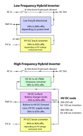
All HF AIO inverters use HV DC node as the central power distribution node, with the exception of AC input to AC output pass through power.

For 240 vac only inverters the HV DC node is about 350-450 vdc. For 120vac inverters the HV DC node is about 250-290 vdc. The HV DC must be high enough voltage to achieve the peak of sinewave AC voltage by the PWM sinewave H-bridge chopper.

There are a lot of ways for HF AIO inverters to 'game' the efficiency specs. PV DC input to AC output is highest efficiency. Battery to AC output is less efficient. Battery charging is even less efficient.

For LF AIO that feed SCC into battery node, the PV to AC output efficiency is worse since there is the compound efficiency loss of the SCC converter and the battery to AC output inverter in series. LF AIO also puts ripple current on battery since battery is used as filter capacitor to smooth out the constant DC current from PV and the 2x AC line frequency ripple current from AC inverter.

Inverter power paths.png
 
Last edited:
Hello Leslie, good to hear from you again.
The 8010 is now known to have a bit of a "personality".
The internal software that makes it go sometimes has a Joe Biden moment.
The guys at the Back Shed Forum have come up with some alternatives using a Nono microthingy that might be of interest.

I bet its warmer where you are right now, we have just had our winter solstice down here, and its cold wet and sky is grey.
Hi Warp,

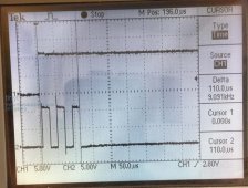
Made me dig up the scope shot of the 3-musketeers.
 

Attachments

  • 3-Musketeers.jpg
    3-Musketeers.jpg
    84.9 KB · Views: 7
All HF AIO inverters use HV DC node as the central power distribution node, with the exception of AC input to AC output pass through power.

For 240 vac only inverters the HV DC node is about 350-450 vdc. For 120vac inverters the HV DC node is about 250-290 vdc. The HV DC must be high enough voltage to achieve the peak sinewave AC voltage by the PWM sinewave H-bridge chopper.

There are a lot of ways for HF AIO inverters to 'game' the efficiency specs. PV DC input to AC output is highest efficiency. Battery to AC output is less efficient. Battery charging is even less efficient.

My Deye 8k is close to 99% efficient when using all the power directly from PV in zero-export to local AC loads. If it cycles through the battery I measure about 91% efficiency.

When I had the Growatt it averaged about 88% efficiency whether from the PV CC directly or cycled through the battery.

This conversation is awesome. Where do all ya'll hang out and talk this stuff on-the-line usually?
 
Last edited:
My Deye 8k is close to 99% efficient when using all the power directly in zero-export to local AC loads. If it cycles through the battery I measure about 91% efficiency.

When I had the Growatt it averaged about 88% efficiency whether from the PV CC directly or cycled through the battery.

This conversation is awesome. Where do all ya'll hang out and talk this stuff on-the-line usually?

Copec, I am curious how you measure efficiency ?

Also, is that with the inverter cold or hot or high Vbatt ?
Low Vbatt ? Full power ? Peak power ? That kind of stuff.

Are you using shunts ?

Thanks,
boB
 
Back
Top