Well that was interesting....
Less than a minute before midnight, my XW-Pro was still running most of the house load, but not exporting. Battery bank is at 53 volts, just 0.5 volt above where it would normally go to standby. It seems we took a short power drop from the grid. But it was not seamless. It caused 2 PC to reboot as well as the Dish Network system. And the lights on the backup also went out and back on. So much for the 8 millisecond transfer, it was more like a full second. I have no idea how long the power was actually out, but it seems like it was just a quick glitch.
This paper regarding Sunny Island describes "high impedance" and "low impedance" grid failures, and reports switchover time of zero to 35 ms depending on inverter model and type of grid failure.
I would think only opening a switch on input of inverter would be "high impedance". Opening circuit anywhere further upstream, whether main breaker or primary of a transformer feeding multiple houses, would have those loads pull the grid down.
What it doesn't describe is how they tested with source drifting out of voltage/frequency spec. In that case, loads still have power and inverter could instantly replace them as it disconnects. Maybe even during a zero crossing?
If source is yanked to zero, it apparently watches for a cycle or two before picking up the load.
This document lists various power line disturbances, and measures classes of equipment expected to have different immunity.
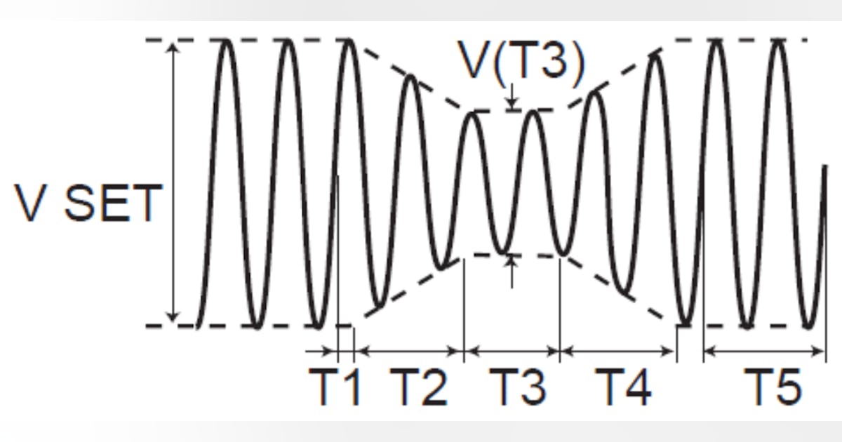
It looks like riding through 20 ms (one line cycle 50/60 Hz) of dropout to 0% voltage and 10 (12 at 60 Hz) cycles to 40% voltage is class 2 requirement.
There is also a 5 second (300 cycle) dropout. Device isn't expected to operate through, but to survive. What it could do is drain any capacitors, but not reset thermal inrush protection. When power suddenly reconnects, there is a surge to recharge capacitors. Not mentioned is if reconnection was not at zero crossing, but rather a contact connecting at peak line voltage.
Read this article online.It seems that everyone is testing IEC61000-4-11 in order to obtain CB certification and international certification (CE marking etc.). The IEC61000-4-...

www.electronicdesign.com
We think of capacitors in power supplies as carrying them through dropouts. That would depend on how much capacitance and how much voltage headroom, since capacitors have to change in voltage to deliver current. A linear supply would have moderate headroom. A switcher for universal 100 ... 240V operation could have more storage when used at higher input voltage, capacitors sized at least to carry specified output during dead time between cycles at 100V, so at least roughly 6 half-cycles with 240V.
And then, there are glitches that crash electronics by an upsetting signal.
Both transients and brief brownout/dropout are conditions electronics is supposed to be tested for. In the case of a PC with variable power consumption, if put in a state of higher consumption would it would drain supply capacitors faster. Wonder if anybody sets that up on purpose for certification testing? I recall the test for zero volt dropouts was a number of cycles, so 35 ms, 2 cycles, shouldn't be enough to power off.
Switchers typically have bridge rectifier into a capacitor at the front end. Instead of UPS, how well would it work to add capacitance, have AC input go through a rectifier into a large capacitor when then feeds DC into the AC power cord of the computer? Idea would be to have much greater power storage, keep it running a couple seconds until inverter takes over. (When charging a capacitor from grid, should have a soft-start mechanism such as thermistor.)