diy solar

diy solar

Anybody tried new JK BMS with inverter communication support?

I guess the pc app is still unusable. I have chained three bmss together - the pc app does 'see' that there are three bmss, but gives an undervoltage error. Perhaps this is because there are 32 cells listed, and 16 of them read 0V. You can see this same series of 0V in andy's video on paralleling. I see 32 cells when two or three bmss are chained together. Capacity is listed as 0Ah no matter what I do. The pc app still only allows you to 'connect' to device #1 - if you select 0, it reverts to 1. I'm using the latest pc app version. Everything reads fine in the mobile app (except for not being able to see parallel status).
 
And they didn’t include the busbars!!!

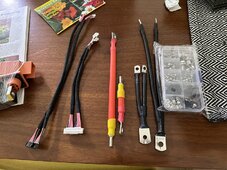
Here are the cables included. 4awg and the negative is 2 7awg.

IMG_3563.jpeg
 
They normally come with the batteries. Might need the longer crossover at the back of the case, depending on how the batteries are orientated and bussbar type.
 
Eel said they were included. I specifically asked about them and wanted them to ship before the Chinese new year as I have a van trip planned for April. It’s going to be tight.
 
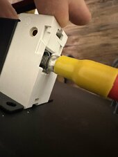
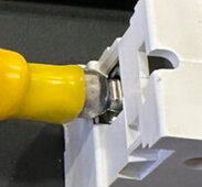
Also the cables included were crimped the wrong way so they don’t fit into the breaker the correct way (it should be flipped 90degrees).

IMG_3565.jpeg

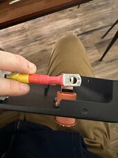
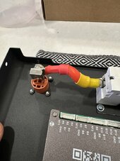
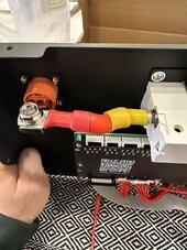
Also the cable from the breaker to the terminal is too long.

IMG_3564.jpeg

I am probably going to upsize these cables anyway as I have a 200amp BMS and I’ll be running 24v. Just a heads up for anyone looking at this for a 48v setup. This was clearly a rush job.
 
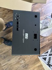
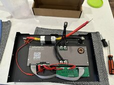
Did a rough assembly of the BMS onto the front panel. The cable CAN work just wish it was a bit shorter. Also did anyone hear about this heater cable? Was is the red and black cable for?


IMG_3584.jpeg

IMG_3585.jpeg

IMG_3586.jpeg

IMG_3588.jpeg

image.jpg
 
That’s a massive ferrule going into that breaker I assume. Did you make that or come with kit. Build is looking great.
 
After few months of idling and messing plus going back and forth with Growatt tech support........I decided to email JKBMS team today and see if they can create an option to set the inverter SOC% to 99% (Never to 100%, custom for Growatt inverter only) when "Controlled Charge Mode" is used........

Wish me luck?
 
Hi All

any one know why we are getting all unknown values even though the CAN is o.k?

View attachment 196537

The Bluetooth code works - suggesting it has to be the GIO Pins wrong, i have tried 16/17 and 01/03 and even swapped them around.

please advise

regards
 
Lunar new year is over in china so I got a reply in the heating function from JK:

For instructions on heating cables, the green 5PIN cable of the heating cable needs to be linked to the heating pad, and the rest of the black and red cables are linked to the smart charger (after the smart charger links the BMS, it detects the temperature of the battery through the BMS, which automatically monitors the charging status of the battery)

Heat Function interface
Description of heating function: Battery temperature is below low temperature charge protection, turn off charging, turn on heating.

Battery temperature is higher than low temperature charge recovery temperature, turn on charging, turn off heating.

Cryogenic charge protection is a parameter that can be set within APP


The heating power depends on the battery voltage and the resistance value of the heating film.

Battery voltage U.

Heating resistance R.

Power equals U*U/R

Heating current I=U/R;

The maximum I (current) of the board design is 3A.

MAX heating power 200W(100W OF B2A8S20P).


The heating pads I got from EEL are going to be too high for this port so I'll end up using a relay to drive the heating pad, though it kinds stinks because it won't register the current used by the heating pad in the app. As for the smart chargers, that requires a customization as it's a comms port not a optocoupler like I first thought.

 
Yes, thank you. JK has a new BMS inverter type gadget... JKBMS 8S 16S 24V 48V 100A 150A 200A 8S-16S Family Energy Storage Lifepo4/Li-ion/LTO Inverter https://srikobatteries.com/?s=jk+inverter+bms&post_type=product

Those only show 8S and higher.

On my 4-8S ones I'm using, I can just not connect some cell leads and tell the software how many cells I've got. I'm wondering if I can do the same with this new type inverter BMS, which currently does not show a 4 count cell setup... ?
 
Last edited:
Back
Top