If you ever need to do a Forced Update, click on this link to acquire your code versus having to contact JK.
https://mirofromdiro.github.io/JK-firmware-code/
https://mirofromdiro.github.io/JK-firmware-code/
I'm sorry but these are 8S-24V and up. There will not likely ever be a 4S-12V version of these.Still wanting to find out from a wisened user if I can use one of these new JK BMSs for a 4S setup?
Those only show 8S and higher. I'd think it's be possible by telling the BNS I've only got 4S
https://srikobatteries.com/?s=jk+inverter+bms&post_type=product
Thank you.
Thanks Steve.I'm sorry but these are 8S-24V and up. There will not likely ever be a 4S-12V version of these.

Oh thats great and can help with downgrades it seems. But where can you get latest firmware? Maybe there is a running source of compilations of all the firmare?If you ever need to do a Forced Update, click on this link to acquire your code versus having to contact JK.
https://mirofromdiro.github.io/JK-firmware-code/
https://drive.google.com/drive/folders/1RsZvSsntvQqFDYC1oDibYVv18V35xeoBOh thats great and can help with downgrades it seems. But where can you get latest firmware? Maybe there is a running source of compilations of all the firmare?
just got the same box deliveredDid a rough assembly of the BMS onto the front panel. The cable CAN work just wish it was a bit shorter. Also did anyone hear about this heater cable? Was is the red and black cable for?
View attachment 194763
View attachment 194765
View attachment 194766
View attachment 194767
View attachment 194768
built the battery today. I had to use the EVA foam and epoxy sheets to get the batteries nice and snug (EVE280V3). There were a few bits and pieces that were a bit dodge, similar cable length issue as nebulight for the breaker to main+ terminal, somewhat fixed by flipping the breaker direction. The two ring terminals soldered to the wires on the top balance PCBs that connect to bat main + and - were a bit shit, I had to swap them for new ring terminals, there were blobs of solder that interfered with the nut so couldn't clamp down nicely.just got the same box delivereddid you use the EVA foam between the cells, the green sheets, or both?
| Function | Victron VE.Can side | Battery side |
|---|---|---|
| GND | Pin 3 | Pin 6 |
| CAN-L | Pin 8 | Pin 5 |
| CAN-H | Pin 7 | Pin 4 |

Доброго дня. Запитайте, возможно, здесьВсем привет.
Я погрузился в новый проект. Взял битый аккумулятор от Tesla 3 (был в идеальном состоянии, ни одной вмятины), в нем стояли заводские элементы CATL 175А, 106шт. нашел еще 4 и сделал аккумуляторы 7х16S. Сохранено 64 кВтч. И я использовал платы PB2A от JK.
Итак, у меня есть 1 ГЛАВНЫЙ (адрес 0) и 6 ВЕДОМЫХ 1-2-3-4-5-6.
Есть некоторые проблемы, и они имеют значение
1) ЕСЛИ одна ошибка BMS останавливает инвертор, и знаете что, он работает. (Пробовал OVTemp и OVP) по любому из протоколов (их около 6 в таблице CAN на выбор)
Все, что он делает, это выдает сумму AMP заряда-разряда (если одна BMS выходит из строя, сумма просто уменьшается) и дает инвертору информацию о плавающем токе в этот момент. Вот и все.
Кроме того, показания температуры абсурдны (на SLAVE BMS не наблюдается повышения температуры, Master BMS имеет среднее значение среди 4 MASTER датчиков), черт возьми!
2) Между BMS существует протокол RS485, а также UART RS485, который можно выбрать в приложении (5–6 протоколов RS485).
Я получил некоторую информацию о батарее в Solarassistant с использованием адаптера CH340 USBtoRS485, но это не вся информация о главном и подчиненном устройствах (она просто похожа на ту, что получает инвертор (средний ток и т. д.)
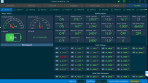
3) Используя тот же преобразователь RS, я попытался подключиться к программе Windows JK BMS Monitor 2.7.0 и смог только просматривать MASTER без редактирования или переключения между всеми подключенными BMS. они отображаются как отключенные
Это так просто – заставить ваше программное обеспечение подключаться к вашим устройствам.
Я бы сказал, что BMS — это ранняя альфа.
View attachment 201356
обновление.
Буду рад, если кто-нибудь поделится своим опытом
Отчет об ошибке BMS => Инвертор (думаю, любой марки)
Программное обеспечение для монитора ПК с более чем 1 BMS
Доброго дня. Запитайте, возможно, здесь, чтобы проверить.
У меня такой же аккумулятор, как 1x16S. Была попытка сделать то же самое, но был эксперимент по протоколу связи с инвертором.
Добрый день. Спросить может быть здесьон тестировал.
У меня такая же батарея, только 1х16S. Ошибки были только тогда, когда был эксперимент по протоколам связи с инвертором.


