skyc
New Member
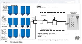
I did the attached diagram for the interconnect agreement based on some examples I have found and I'm curious how it compares to some of you that have done their own interconnect submission and if you think it will work? The sample line diagram that is an option to select as representative is also attached, which might work as well - assuming inverter can equal microinverter?
Additionally, thoughts on AC disconnects with microinverters - from what I've found, not required as the shutoff is built into the microinverters.


Additionally, thoughts on AC disconnects with microinverters - from what I've found, not required as the shutoff is built into the microinverters.
") I think that the PGE online application program may provide samples. Trying to understand some things before starting an application.
I think that the PGE online application program may provide samples. Trying to understand some things before starting an application.