diy solar

diy solar

Chargery BMS, DCC (Solid State Contactor) thread.

I was looking at the gigavac gv series which is the kilovac equivalent. Problem is, Jason says the amp rating for the control circuit is 3a. the max needed by the contactor is 3.8. is there some hocus pocus i can do with resistors and capacitors to make it work without stressing the BMS?
I tested with Kilovac, Gigavac, Dongya & Energy Saver Relays in single & dual relay mode without issue. I think Craig (former moderator here) did a couple of other brands and we also did different Solid State Contactors as well.

With relays there is the DELAY BOARD which goes between the relays & BMS that can service the Precharge requirements.
An Opto-Coupler can also be used so that you use One Relay as opposed to two.

IN Fact, because I am rural & remote and Stuff can Hit The Fan and most often at the worst possible time, I have a "Board" already setup with two Gigavac Energy Savers, delay board, and Shunt, all setup and ready as an Emergy backup "relay rig". I did these up before I switched to DCC so I kept one for backup just in case a DCC pooches on me. None have.
ive read too many complaints about chargery’s precharge. whether or not those issues are resolved or not, i don’t know. i already have a precharge circuit, and frankly don’t want that automated with the BMS. When (hopefully rarely) the BMS has to engage for a fault condition, i want it to stay that way until i can manually intervene. If im getting false alarms, i should be able to resolve the problem; otherwise, it should just hum along the way its supposed to. Not interested in more complexity.

When i mentioned capacitor and resistor i was talking about something in line on the charge/discharge control circuit. I want to have extra power available on that ciricuit when the circuit does need to engage and needs that 3.8a to feed the contactor coil. It only needs it for 75 miliseconds (or a very low time, don’t remember if the spec sheet said miliseconds or 100ths).

edit: would love to have other EEs chime in on this idea, too. obviously i don’t know exactly how to design a circuit like this. what size resistor should I use? What size capacitor to be able to supply the necessary current?

Also, I presume I need normally open contactors. Is that correct?
 
Last edited:
N.O. or normally open relay/contactor will open=disconnect switched terminals when power is removed from the coils, excepting fancy circumstances like super duper surge of amps.

this type is useful for situations where an appropriate reaction to “oh no” is just disconnect the battery from the load

gigavac normally open contactors are what i’m targeting for safety disconnects with my current DIY pack design

edit:

for precharging inverter capacitors, i have targeted wirewound 50-100W resistors to restrain the greatly feared Ampere surge

e.g. https://www.amazon.com/Yohii-Aluminum-Resistors-Housed-Wirewound/dp/B07DKF99BT

depending on battery system voltage maybe connect two in series
HI CC,

trying to steer the answers away from precharge. this is not my concern. My concern is that the relay coils can require up to 3.8a @ 12v to engage (meaning to close a normally open contactor), while Jason has stated that the BMS is rated for 3a @ 12v on the control circuit output. Notice the deficit?

With that said, 3.8a is the max that the coil could require to engage.

What I am inquiring about is capacitance to fill that potential 75ms surge to 3.8a.
 
This is OFF Topic for this thread... but...
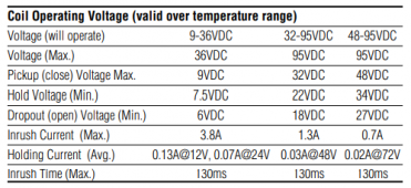
I myself did not try working with the "Gigavac" GV series but with the Kilovac EV series which have a coil that starts at 9V as opposed to 12V but I would not conclude that made a difference, maybe it did. The Dongya DHV's also start at 9V but still have a starting current of 3.8A with a hold current of 0.16A @ 12V. I would assume it's pretty much universal for this design, unless you get into crazy bucks stuff.

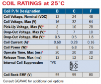
Looking at the Gigavac GV200 https://www.gigavac.com/sites/default/files/catalog/spec_sheet/gv220.pdf
the PDF doesn't show the inrush current for the coil sadly
1625501291213.png

Notation 6: Contactor is operated by a coil that changes resistance with temperature. Since Pick-up Current, Coil Current and Coil Power are specified at Nominal Voltage, they will be lower than indicated at temperatures above 25°C and higher than indicated at temperatures below 25°C. Similarly, Pick-up and Drop-out Voltages will be higher than indicated at temperatures above 25°C and lower than indicated at temperatures below 25°C

The Kilovac EV200 LINK HERE LINK HERE
1625501230170.png
 
The easiest and safest way to drive that extra current is with another relay, usually solid-state (to keep the power usge down). that's what I did - an SSR that drives the bigger relay. The large relay needs the full voltage and current in order to properly latch. They explicitly say not to put a resistor or whatever in front.
 
The easiest and safest way to drive that extra current is with another relay, usually solid-state (to keep the power usge down). that's what I did - an SSR that drives the bigger relay. The large relay needs the full voltage and current in order to properly latch. They explicitly say not to put a resistor or whatever in front.
i don’t plan on using a latching relay. you’re saying i need another relay to drive the relay? Perhaps I don’t need a resistor and just need a capacitor in front of the gigavac coil activation input? What size capacitor would fill the potential deficit? what inrush would it cause? I can’t see how this is unsafe. its exactly what the electrical components i’m talking about are designed to do. we’re talking about a .8a 75ms deficit to fill. seems much more simple to serialize a capacitor in the circuit rather than run additional power wiring and fuse for control of a control circuit.
 
The easiest and safest way to drive that extra current is with another relay, usually solid-state (to keep the power usge down). that's what I did - an SSR that drives the bigger relay. The large relay needs the full voltage and current in order to properly latch. They explicitly say not to put a resistor or whatever in front.
So, if i follow the...advice...given here (step 2) and multiply the full load amps (3.8) by 2650, then divide that number by supply voltage (12) i get 839.1666666 microfarads. meaning i need a capacitor at or above that size. Is that accurate? Can anyone explain?
 
The thing you need to prevent is slow voltage rise on the contactor. It needs the full voltage & amperage instantaneously. Just a capacitor won't enable this. You'd need something that buffers up the energy (at a rate below 3 amps) and then releases it to the contactor in combination with connecting the contactor to supply power. A small cheap SSR (or opto-coupler) is easy enough and requires no engineering :)
 
the high Ohms resister jumped across the switch would slowly drain the pack flat if left connected for long periods without charging would it not?
Eventually it would, but at such a low draw it'd take years on my 64kwh bank to even be noticeable, the BMS draws more than the resistor. On a small bank like for a ebike it'd wouldnt be such a good idea though and it would indeed draw down a battery.

I also found that the surge on my gigavac relays exceeded what the chargery could handle so I ended up using 48v coil relays with a interposing crydom SSR that could trigger with the 12v from the BMS but pass through the 48v nominal from the battery bank. The SSR uses only just a few milliwatts to actuate and hold, the gigavacs after actuating use about 1-1.5 watts to hold closed.

Using a SSR interposing relay is a better solution anyway as it reduces the power flowing through the Chargery to very little and thus extends its lifespan.
 
Last edited:
Eventually it would, but at such a low draw it'd take years on my 64kwh bank to even be noticeable, the BMS draws more than the resistor. On a small bank like for a ebike it'd wouldnt be such a good idea though and it would indeed draw down a battery.

I also found that the surge on my gigavac relays exceeded what the chargery could handle so I ended up using 48v coil relays with a interposing crydom SSR that could trigger with the 12v from the BMS but pass through the 48v nominal from the battery bank. The SSR uses only just a few milliwatts to actuate and hold, the gigavacs after actuating use about 1-1.5 watts to hold closed.

Using a SSR interposing relay is a better solution anyway as it reduces the power flowing through the Chargery to very little and thus extends its lifespan.
As I recall from way back when, this is where we started to lean on the Opto-Couplers to handle the triggering on the bigger relays, before we got Jason to design the DCC's.

ANYWAYS: THE TOPIC IN THIS THREAD IS

Chargery BMS, DCC (Solid State Contactor) thread.​

 
Solid State Contactors are really nice, no moving parts

the thing with the really close terminals totally turned me off of the device. i wonder if the terminals are more widely spaced now..

i want to use DCC due to power draw reduction
 
Solid State Contactors are really nice, no moving parts

the thing with the really close terminals totally turned me off of the device. i wonder if the terminals are more widely spaced now..

i want to use DCC due to power draw reduction
i was turned off of them due to the seemingly poorly implemented precharge among other things. just wasnt worth jumping into the deep end on, for me.
 
I’d would also like to use the DCC that Jason designed. Problem is that it only can handle 100v. My solar array is over 100v, not by much but it is. It has to be to properly charge16s Li-ion.
Isn’t it better to disconnect the charge from the solar array before it enters the charge controller. wouldn’t that be easier on the charge controller than disconnecting the power coming out of the chargecontroller into battery. When I shutoff my Outback fm80 chargecontroller it is recommended to disconnect solar before disconnecting the battery and that makes sense so the charge controller stops charging before its instantly turned completely off.
Am I going about this wrong, is there a better way. At the moment I’m stuck using high voltage ev realty’s that get hot and use way to much power.
If this post doesn’t belong here please tell me where to put it
The DCC has nothing to do with what is going into the SCC. You either have a 12V.24V/48V battery System.

The entire charge controller and disconnecting panels nonsense has been beaten to death several times already on this forum... Leave that dead donkey alone, Search the forum and follow those threads or start another one to start the whole shtick up yet again.

Jumping in "Deep End" with a DCC ????
300A DCC = 89.90 Kilovac/gigavac EVE type relay = 180+/- USD
And you only need one for Common Port.

I have 5 BMS8T's with DCC300's (First issue as well) and No Problems, Inverter has been shutdown, caps drained and started on LFP no issues and it has Monster Caps which really suck it in on startup.
 
I have to say that the DCC is an interesting device, especially seeing the price.

When we developed the 123\PowerSwitch, we designed it specifically for 48V systems in mind, so 100A would be enough because most customers are below 5kW. Of course it can be used with 12 and 24V systems. The voltage drop for the PowerSwitch at 100A is about 80mV, so fan cooling was not required and even 200A was possible for some time without fan cooling.

What are your experiences with the DCC, can it keep working at maximum load at environmental tempratures around 40-45 degrees?
 
The DCC has nothing to do with what is going into the SCC. You either have a 12V.24V/48V battery System.

The entire charge controller and disconnecting panels nonsense has been beaten to death several times already on this forum... Leave that dead donkey alone, Search the forum and follow those threads or start another one to start the whole shtick up yet again.

Jumping in "Deep End" with a DCC ????
300A DCC = 89.90 Kilovac/gigavac EVE type relay = 180+/- USD
And you only need one for Common Port.

I have 5 BMS8T's with DCC300's (First issue as well) and No Problems, Inverter has been shutdown, caps drained and started on LFP no issues and it has Monster Caps which really suck it in on startup.
Maybe im confused. Forgive me but I wanted to at least respond to ya. What happens when the bms disconnects due to battery being drained to low. How do I charge the batteries back up if using common port and it has discharge and charge disconnected. I found another post that was about common/separate port and I asked there if this is off topic for this thread.
If this is talked about somewhere else please direct me to it
 
Last edited:
Back
Top