diy solar

diy solar

Daly smart BMS

I'm looking for advice on my setup. I have 8s 24v system with 3.2v Catl cells, and i just received my Xenes 150a bms (copy of the Daly). Finally managed to connect via urt cable, but the numbers are strange. It says two of the cells are at 5.0 volts, and the rest are ok. Could someone take a look at the photos and tell me what to do. I have not charged them yet, top balanced them until all were 3.27v. I have Powland hybrid inverter which i'm going to connect battery to.

Thanks for the advise.

Edit: well those pics suck, i'll take better ones if needed.
Ordinarily odd cell voltages are a sense wire connection problem. Those are not.
Contact the vendor and get a new BMS (unless you hooked two wires up to a 5v power supply).

FYI, 3.27v is not a top balance. The word top has meaning in this context.

I also recommend changing balance voltage to 3.4v, not 3.2v (after you top balance).
 
Last edited:
Oh, ok. I will send it back. i might even think about other bms, heard that overkill might be good, just hard to find in europe.
 
Oh, ok. I will send it back. i might even think about other bms, heard that overkill might be good, just hard to find in europe.
Overkill is actually a JBD BMS that has additional testing and of course technical support.


You can purchase direct.


That would be the equivalent JBD that Overkill sells for 24v.
 
Do you have a picture of your new leads?
What size wire?
Don't forget banana plugs aren't usually as bad, but they certainly aren't good.

Less than 2 amps at 3.65v is about 7 watts, it'd have to be awfully thin wire to get warm.
Certainly making the terminal connections better is a step in the right direction. What does your meter read as the resistance on you new connections?
ps and leads.jpg

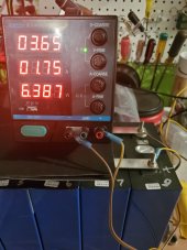
OK, I stacked the PS on top of the bank of batteries to get the PS display and all 4 connectors in the pic. My on-hand wire choices in stranded were 6 and 16ga. I chose the 16ga which is rated for 10A. You can see I put ring terminals on both end of the wire, i.e. I am not using banana plugs.

Here is where the mysterious lack of charging takes another turn.

To recap, the voltages were 3.3 from factory, 3.36 after individual cell charging, and 3.40 after 9 days charging as a bank. Guess what. After I made the changes to the wiring yesterday and charged the batteries for another day with the new wiring, the voltage DROPPED to 3.38. I checked the first and last cell in the battery bank to make sure just the last cell (used for all measurements) wasn't wonky.

The PS showed 3.65V, 1.78A and 6.5W yesterday and per the picture, it is now 1.75 and 6.4. So even though the battery bank dropped voltage, the charger is putting out even less.

I hadn't measured resistance. What two points do you want the resistance measured across? I didn't know there were any connections or wire distances involved here to get a voltage drop.

Thanks
 
That is still REALLY poor current ..... So, you are still loosing power across the leads or the power supply has a problem.
What is the voltage directly at the power supply VS at the battery connections ..... this would be how much voltage you are loosing across the leads.
I would want at least 10 gauge to prevent voltage drop and would have gone with your 6 gauge since you have it already.

edit: just so you know why we are pushing this so hard .... we have seen this problem over and over again.
The wires inside the power supply will come into play I bet they are smaller than 16 GA. catch 22.
 
That is still REALLY poor current ..... So, you are still loosing power across the leads or the power supply has a problem.
What is the voltage directly at the power supply VS at the battery connections ..... this would be how much voltage you are loosing across the leads.
I would want at least 10 gauge to prevent voltage drop and would have gone with your 6 gauge since you have it already.

edit: just so you know why we are pushing this so hard .... we have seen this problem over and over again.
This is my second power supply and the first one didn't produce any more power than this one. DrMeter sent me a replacement new PS, so it is either PS design or something other than the PS.

I measured the output at the PS supply connectors, 3.74. Measured the power where connected to the first cell, 3.38. I can't fathom how it could drop in that short of distance, especially since the ga is appropriate to the amperage. This means the direct ring terminal connection with 16ga is performing lower than the supplied alligator clips. I doubt their lead wire is greater than 16ga.

The 6ga was bought for my install, not really extra wire laying around. I didn't want to put ends on it until I know how much of it I will need and what connectors it will need on it. I can run to the local hdwe store and buy a piece of 10ga.
 
The wires inside the power supply will come into play I bet they are smaller than 16 GA. catch 22.
My previous PS, before dying, was temporarily set to constant amperage at full current, 10A. People have said this PS can produce 10A indefinitely it seems the "internal" wiring should be adequate for handle 10a.

If instead of running the PS at 3.65 constant voltage, what would happen if I ran it at 10a constant amperage and manually monitored the voltage?

BTW, this is the Will Prowse endorsed model :)
Have you seen a 100 amp current shunt made out of brass and copper? They get a 50 mv drop across a short piece of copper (like 3/4" long) much bigger than 16 ga.
 
This is my second power supply and the first one didn't produce any more power than this one. DrMeter sent me a replacement new PS, so it is either PS design or something other than the PS.

I measured the output at the PS supply connectors, 3.74. Measured the power where connected to the first cell, 3.38. I can't fathom how it could drop in that short of distance, especially since the ga is appropriate to the amperage. This means the direct ring terminal connection with 16ga is performing lower than the supplied alligator clips. I doubt their lead wire is greater than 16ga.

The 6ga was bought for my install, not really extra wire laying around. I didn't want to put ends on it until I know how much of it I will need and what connectors it will need on it. I can run to the local hdwe store and buy a piece of 10ga.
It's not the ability to carry the amperage .... It's that you are dropping so much voltage across the leads that you don't have hardly any difference of potential by the time you get to the battery .... therefore, very low current.

I've seen this same scenario many times, and by your own voltage readings you can see that you are loosing too much voltage across the leads.

Find a chart about wire size VS voltage drop instead of amp carrying capacity.
Perhaps I am still not getting it, but I checked a DC wire chart and it shows that 16ga can carry 10a with under 3% drop up to 6'. 10% drop at 20'.
Have you seen a 100 amp current shunt made out of brass and copper? They get a 50 mv drop across a short piece of copper (like 3/4" long) much bigger than 16 ga.
I have the Victron shunt that pairs with the BMV712. Haven't used or installed it yet.
 
Perhaps I am still not getting it, but I checked a DC wire chart and it shows that 16ga can carry 10a with under 3% drop up to 6'. 10% drop at 20'.

I have the Victron shunt that pairs with the BMV712. Haven't used or installed it yet.
If you don't get it by now, I don't know what to tell you ...... You can see by your own voltage readings that you are dropping too much voltage across the leads. Voltage drop is caused by the accumulation of resistance ... resistance from the contact points, resistance from the wire, resistance from the crimp connections.

You are dropping too much voltage across your leads.
 
My previous PS, before dying, was temporarily set to constant amperage at full current, 10A. People have said this PS can produce 10A indefinitely it seems the "internal" wiring should be adequate for handle 10a.

If instead of running the PS at 3.65 constant voltage, what would happen if I ran it at 10a constant amperage and manually monitored the voltage?

BTW, this is the Will Prowse endorsed model :)
Yep you can do that and in fifteen minutes can have puffy cells because the upper knee can happen very fast and cause the electrolyte to turn into gas. A 3% drop on 6' of wire which is what you have about that is temp dependent also would give you from 3.65 V to 3.54 V
 
My previous PS, before dying, was temporarily set to constant amperage at full current, 10A. People have said this PS can produce 10A indefinitely it seems the "internal" wiring should be adequate for handle 10a.

If instead of running the PS at 3.65 constant voltage, what would happen if I ran it at 10a constant amperage and manually monitored the voltage?

BTW, this is the Will Prowse endorsed model :)
Yes, I have the identical model with another name on the case. You should be putting out at least close to 10 amps. I assume you maxed out the current knobs?

You should be able to short the ends together and get 10 amps. I know 12 gauge can do it.

Edit to add, if you want pictures of an identical supply doing 10 amps, here you go:


Sad to say, but unless the current knobs are turned down, you likely have a second bad supply.
 
Last edited:
Yes, I have the identical model with another name on the case. You should be putting out at least close to 10 amps. I assume you maxed out the current knobs?

You should be able to short the ends together and get 10 amps. I know 12 gauge can do it.

Edit to add, if you want pictures of an identical supply doing 10 amps, here you go:


Sad to say, but unless the current knobs are turned down, you likely have a second bad supply.
Hello, reporting in with current status.

In hopes of getting this to work, it seemed the next step was to upgrade the gauge. So I hopped in my putt putt and went to the local hdwe store. Sad to say, they had stranded down to 14ga, to get 12ga they had power cable, i.e. 12/3. To get 10ga I would have had to buy a dryer cable, 3' for $27. No way Jose.

So, I bought the 12ga power cable and split out two wires and put new ring terminals on the 12ga wire.

The instructions for the PS say for constant voltage, turn on the PS, turn the amps to full, and then set the voltage to the desired amount, and then connect the battery. The steps work fine until connecting the battery. The PS immediately jumps into constant amperage mode, giving me 10.X amps and it says 3.52V. I repeated the steps several times and the results didn't change. I referred back to the manual, and the steps to force constant voltage aren't working.

The "good" news is that it is cranking out 10.X amps...so it isn't a matter of the PS being unable to.

I guess as long as the charge rate is a low 3.52V that letting it run that way for awhile isn't going to harm anything? But that still doesn't allow me to use the PS as I Thought I would be able to, i.e. set it to 3.65v and let it top balance.

What idiotic thing am I doing now, why won't it allow me to force CV vs. CA?

Thanks brainiacs.
 
If you don't get it by now, I don't know what to tell you ...... You can see by your own voltage readings that you are dropping too much voltage across the leads. Voltage drop is caused by the accumulation of resistance ... resistance from the contact points, resistance from the wire, resistance from the crimp connections.

You are dropping too much voltage across your leads.
Thanks for making your point and below are my results....I am either having an operator error or?? The PS can send 10A to the battery, but the issue is at what voltage...thanks kind sir.
 
Hello, reporting in with current status.

In hopes of getting this to work, it seemed the next step was to upgrade the gauge. So I hopped in my putt putt and went to the local hdwe store. Sad to say, they had stranded down to 14ga, to get 12ga they had power cable, i.e. 12/3. To get 10ga I would have had to buy a dryer cable, 3' for $27. No way Jose.

So, I bought the 12ga power cable and split out two wires and put new ring terminals on the 12ga wire.

The instructions for the PS say for constant voltage, turn on the PS, turn the amps to full, and then set the voltage to the desired amount, and then connect the battery. The steps work fine until connecting the battery. The PS immediately jumps into constant amperage mode, giving me 10.X amps and it says 3.52V. I repeated the steps several times and the results didn't change. I referred back to the manual, and the steps to force constant voltage aren't working.

The "good" news is that it is cranking out 10.X amps...so it isn't a matter of the PS being unable to.

I guess as long as the charge rate is a low 3.52V that letting it run that way for awhile isn't going to harm anything? But that still doesn't allow me to use the PS as I Thought I would be able to, i.e. set it to 3.65v and let it top balance.

What idiotic thing am I doing now, why won't it allow me to force CV vs. CA?

Thanks brainiacs.
The power supply only can give you 10 amps the batteries can take a lot more than the power supply can put out so to keep the power supply from overloading it will change to CA mode if it did not do that it will burn up as the batteries can take hundreds of amps.
 
Hello, reporting in with current status.

In hopes of getting this to work, it seemed the next step was to upgrade the gauge. So I hopped in my putt putt and went to the local hdwe store. Sad to say, they had stranded down to 14ga, to get 12ga they had power cable, i.e. 12/3. To get 10ga I would have had to buy a dryer cable, 3' for $27. No way Jose.

So, I bought the 12ga power cable and split out two wires and put new ring terminals on the 12ga wire.

The instructions for the PS say for constant voltage, turn on the PS, turn the amps to full, and then set the voltage to the desired amount, and then connect the battery. The steps work fine until connecting the battery. The PS immediately jumps into constant amperage mode, giving me 10.X amps and it says 3.52V. I repeated the steps several times and the results didn't change. I referred back to the manual, and the steps to force constant voltage aren't working.

The "good" news is that it is cranking out 10.X amps...so it isn't a matter of the PS being unable to.

I guess as long as the charge rate is a low 3.52V that letting it run that way for awhile isn't going to harm anything? But that still doesn't allow me to use the PS as I Thought I would be able to, i.e. set it to 3.65v and let it top balance.

What idiotic thing am I doing now, why won't it allow me to force CV vs. CA?

Thanks brainiacs.


1. Wire all your cells in parallel. Note: If your cells are more than about .15V different, it is probably best to charge the lower cells to about the same as the higher cell(s) before paralleling them. To do this, parallel the lower voltage cells and use this top balance procedure to get them close to the voltage of the higher cells and then top balance them all)
2. Before hooking the power supply to the cells, set the power supply to .2C or less of the combined AH of the cells. This will almost always turn out to be the max current setting of the power supply.
3. Set the voltage on the power supply to 3.65V.
4. Hook the negative lead to the negative pole of one end of the series of cells and the positive lead to the positive pole at the other end of the series of cells as shown in the image on the right (Be sure to get the polarity correct). The diagonal hook-up helps balance the resistance between the power supply and the individual cells.
5. At this point the cells are all being charged to 3.65 volts. Depending on the SOC of the cells, your power supply might be current limited and the voltage on the display will be less than 3.65 volts. Do not adjust the voltage!
 
Back
Top