diy solar

diy solar

Daly smart BMS

Hi @Stepandwolf ,
how is your comment related to this BMS?
note: many lab power supplies have relative low power. So it is not abnormal it takes ages to charge a cell or battery with it... But at least I expect it should run at its max power (as the internal resistance of the cells is very low). What was the current that it managed to provide with the cells at 3.3-3.4A? Does it run higher currents if you increase the voltage to 3.65V - at your own risk ;-). Sometimes the voltage provided is not very accurate and sometimes the current limiting functionality is also not working very great (staying far from the max power). And on my PS I need to take higher current from the back of the PS; front is limited to 5A.
 
Hi guys, I wrote earlier that my Dr. Meter PS had died. The good news is that they are sending me a new one, expected to arrive today.

Should I once again try to bring up each individual cell from 3.3V to 3.5V and then top balance the whole pack with the cells connected in parallel and then connect the BMS?

I was so discouraged that it took the PS two days to raise the voltage from 3.3 to 3.4V before I gave up. Perhaps I wasn't using the PS correctly. I thought setting the PS to constant voltage of 3.5V would cause the PS to run at full 10A until it reached 3.5V but it doesn't seem to work that way. Seems it is sensing it is "close" and tapers the amperage to next to nothing, essentially keeping it from ever reaching 3.5V.
Ohms law is what tapers current when you get close. It is not sensing, it is instead obeying the laws of nature.

Better cables can help by a LOT. Some people went from 4 amps to 10 just by getting rid of the cheap cables and alligator clips. Again, ohms law.
Hook up your cells in series and charge them with a BMS. When one cell trips your high voltage disconnect, then put them in parallel to top balance them. Make better cables (10 gauge wire and ring terminals) to keep it putting out maximum amps as long as possible.
Charging in series with a BMS allows you to put in 4 or 8 times as much power (depending on 12 or 24v battery). In other words in series, each cell gets 10 amps, in parallel you take that 10 amps and each cell gets 2.5 or 1.25 amps.
 
Hi @Stepandwolf ,
how is your comment related to this BMS?
note: many lab power supplies have relative low power. So it is not abnormal it takes ages to charge a cell or battery with it... But at least I expect it should run at its max power (as the internal resistance of the cells is very low). What was the current that it managed to provide with the cells at 3.3-3.4A? Does it run higher currents if you increase the voltage to 3.65V - at your own risk ;-). Sometimes the voltage provided is not very accurate and sometimes the current limiting functionality is also not working very great (staying far from the max power). And on my PS I need to take higher current from the back of the PS; front is limited to 5A.
Hello Walter, per my 3rd sentence, this is preparation to connecting the BMS or as suggest by some, to start with the BMS.

I never combined the batteries into a bank, only solo. First cell charged for 2 days and went from 3.3 to 3.4v. Amp/watt was very low but I didn't record the values. When connecting to the second cell, was when the PS died so that is as far as I got.

It has been reported that my PS can run at full 10A continuous without having a hissy fit. My PS only has front outputs but I will change from the provided alligator clips to 10ga.

Thanks
 
Ohms law is what tapers current when you get close. It is not sensing, it is instead obeying the laws of nature.

Better cables can help by a LOT. Some people went from 4 amps to 10 just by getting rid of the cheap cables and alligator clips. Again, ohms law.
Hook up your cells in series and charge them with a BMS. When one cell trips your high voltage disconnect, then put them in parallel to top balance them. Make better cables (10 gauge wire and ring terminals) to keep it putting out maximum amps as long as possible.
Charging in series with a BMS allows you to put in 4 or 8 times as much power (depending on 12 or 24v battery). In other words in series, each cell gets 10 amps, in parallel you take that 10 amps and each cell gets 2.5 or 1.25 amps.
That is the first I have heard that suggestion, i.e. BMS first and then top balance in parallel. Your saying my measly 10A is better managed with the BMS and then bypass it for balancing. makes sense, thanks!
 
Hi everybody, i am new to this forum and have a question concerning the ad of Daly for the smart BMS. There seems to be digital io that can be customised. Has somebody any experience with these IO ?
 
Hi guys, I wrote earlier that my Dr. Meter PS had died. The good news is that they are sending me a new one, expected to arrive today.

Should I once again try to bring up each individual cell from 3.3V to 3.5V and then top balance the whole pack with the cells connected in parallel and then connect the BMS?

I was so discouraged that it took the PS two days to raise the voltage from 3.3 to 3.4V before I gave up. Perhaps I wasn't using the PS correctly. I thought setting the PS to constant voltage of 3.5V would cause the PS to run at full 10A until it reached 3.5V but it doesn't seem to work that way. Seems it is sensing it is "close" and tapers the amperage to next to nothing, essentially keeping it from ever reaching 3.5V.
Your power supply is sensing the voltage at the power supply terminals and does not correct for voltage drop on the wire you connect to the battery unless it is a good power supply with remote sensing (4 wires) it will also work better if you use larger wire going to the battery and NO alligator clips but use ring terminals.
 
I agree on the ring terminals. Went from the crappy cable with croc clips supplied with the psu to 6ga wire and hydraulically crimped lugs, and the current went from 3.5A to 15A (limit of my supply) just with a change of cable.

Charging in series first is more effecient - 14.6V at 15A is more power than 3.65V at 15A (219W vs 54.75W). My PS maxes out at 15A.
 

fguiot​

Solar Enthusiast

Searched this site and found something valuable.
A very good explanation about the sinowealth and the explanation about the parameters abbreviations.
So that better understanding and settings ensure more safety and operation of the bms,
Thank you so much
 
Last edited:
Your power supply is sensing the voltage at the power supply terminals and does not correct for voltage drop on the wire you connect to the battery unless it is a good power supply with remote sensing (4 wires) it will also work better if you use larger wire going to the battery and NO alligator clips but use ring terminals.
Well guys....has been over a week. The charger went from charging 5w, and now it is down to 1.5w...yes, dribbling power into the 8 cells. I haven't stopped the charge yet so I don't know what the cells were charged to. I did measure the cells while being charged, and it showed 3.55v, so the charger isn't even attempting to charge at a value close to the 3.65v setting.
 
Did you read the voltage setting with a DVM .... set to 3.65 on the supply and then read the voltage? If it's different then you have to make sure which one is correct.

If you disconnect the leads and you have 3.65 volts on the leads with no current .... you probably have some bad connection causing voltage drop across the leads.
 
Well guys....has been over a week. The charger went from charging 5w, and now it is down to 1.5w...yes, dribbling power into the 8 cells. I haven't stopped the charge yet so I don't know what the cells were charged to. I did measure the cells while being charged, and it showed 3.55v, so the charger isn't even attempting to charge at a value close to the 3.65v setting.

Do you happen to have a picture of your cables connected to the cells?
Often, a picture is worth a thousand words.
 
OK guys....first of all, the physical setup. I used factory bus bars with SS studs and nuts. I used the default power leads with alligator clips that came with the PS. Yes, I could have used ring terminals. I just don't think that is the reason things are going poorly, in my estimation.

Cells from Lishen were 3.3v. I individually charged the cells with the same PS after 2 days getting them to 3.36. This is the point where I put them into a parallel setup and setup the charging as described above.

When I first connected the PS, I set it to constant 3.65v. The initial readings 8 or 9 days ago was 1.52a and 5.53w. Today, when I disconnected the charger, it read 1.35a and 1.3w. Measuring the first cell, it is now 3.4V. So after 9 days on the charger, the voltage went from 3.36 to 3.4.

How do I ever get to 3.65 to top balance?

Bob, when I checked the PS output voltage with no load, it shows 3.74v, so the output was over the intended 3.65. My desire is it would use the full 10a output it is rated at until the charge got near or reached the 3.65v setting. It doesn't seem to use it's full output whether in an 8-cell bank or when connected to a single cell.

Thanks guys!

Replace those leads .... you will be surprised.
 
OK guys....first of all, the physical setup. I used factory bus bars with SS studs and nuts. I used the default power leads with alligator clips that came with the PS. Yes, I could have used ring terminals. I just don't think that is the reason things are going poorly, in my estimation.

People with lots of experience are telling you to replace the leads.
Replace the leads. Seriously.

If you are in the USA and you just don't want to spend the money on a crimp tool, crimp connectors, and wire, let me know. I can send you some.
 
The original leads have too much voltage drop. These need to be replaced with wires much larger.
 
OK guys....frankly, I didn't think there would be that much loss with the leads I had. So, I grabbed some wire, ring terminals, and a crimper and made some leads special for this project. While I was at it, probably something that made more difference was my battery posts. I only finger-tightened the nuts. This time I took a wrench to them and snugged them up....so....are you ready....drum rolll...

We made a whopping leap from 1.35A to 1.78A I bet most of that improvement was from tightening the nuts, not the ring terminals.

I am not an EE, but it seems the stock leads with alligator clips weren't the limitation. If something can carry the current without warming up, then the connector and wire is adequate.

Hoping there is a plan B!

Thanks
Do you have a picture of your new leads?
What size wire?
Don't forget banana plugs aren't usually as bad, but they certainly aren't good.

Less than 2 amps at 3.65v is about 7 watts, it'd have to be awfully thin wire to get warm.
Certainly making the terminal connections better is a step in the right direction. What does your meter read as the resistance on you new connections?
 
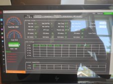
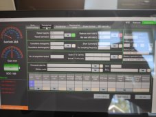
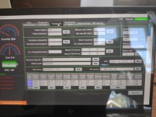
I'm looking for advice on my setup. I have 8s 24v system with 3.2v Catl cells, and i just received my Xenes 150a bms (copy of the Daly). Finally managed to connect via urt cable, but the numbers are strange. It says two of the cells are at 5.0 volts, and the rest are ok. Could someone take a look at the photos and tell me what to do. I have not charged them yet, top balanced them until all were 3.27v. I have Powland hybrid inverter which i'm going to connect battery to.

Thanks for the advise.

Edit: well those pics suck, i'll take better ones if needed.
 

Attachments

  • IMG_20210716_105527.jpg
    IMG_20210716_105527.jpg
    178.3 KB · Views: 24
  • IMG_20210716_105545.jpg
    IMG_20210716_105545.jpg
    157.2 KB · Views: 24
  • IMG_20210716_105554.jpg
    IMG_20210716_105554.jpg
    161 KB · Views: 23
Back
Top