You are using an out of date browser. It may not display this or other websites correctly.
You should upgrade or use an alternative browser.
You should upgrade or use an alternative browser.
dc power is not working properly
- Thread starter hammerhead22!
- Start date
acdoctor
Solar Enthusiast
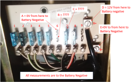
Can you meter 12 from B+ to chassis?
FilterGuy
Solar Engineering Consultant - EG4 and Consumers
Measure C without the fuse installed.
FilterGuy
Solar Engineering Consultant - EG4 and Consumers
Correct.should the battery neg run through the shunt before connecting to the B- lug???
hammerhead22!
New Member
- Joined
- Nov 27, 2021
- Messages
- 14
just to clarify the battery already is connected to the bottom lug of the shunt by itself.
i should now connect the neg cable going to the dc lug to the top side of the shunt and then to the lug
i should now connect the neg cable going to the dc lug to the top side of the shunt and then to the lug
FilterGuy
Solar Engineering Consultant - EG4 and Consumers
hammerhead22!
New Member
- Joined
- Nov 27, 2021
- Messages
- 14
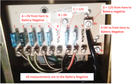
A 0V
B 0V
C 12+
D 12+
E 0V
B 0V
C 12+
D 12+
E 0V
hammerhead22!
New Member
- Joined
- Nov 27, 2021
- Messages
- 14
to late today to get a bus bar i will do it first thing in the morning and follow your corrections in the morning.
if i am still having problems i will post tomorrow
thanks for all of your help it is greatly appreciated
if i am still having problems i will post tomorrow
thanks for all of your help it is greatly appreciated
FilterGuy
Solar Engineering Consultant - EG4 and Consumers
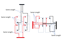
BTW: The battery arrangement will work but it would be better with one of these two connection schemes:

This helps ensure that the load and charge on each of the batteries is balanced. (There is some debate as to whether this makes a big difference on LiFePO4... but I always try to be careful with balancing the battery connections)

This helps ensure that the load and charge on each of the batteries is balanced. (There is some debate as to whether this makes a big difference on LiFePO4... but I always try to be careful with balancing the battery connections)
FilterGuy
Solar Engineering Consultant - EG4 and Consumers
acdoctor
Solar Enthusiast
So I got a IPad so I could read the door. It said 1 through 6 are powered from converter. 7 through 9 are connected to the battery connections B+ as you are calling it. Did you disconnect the converter from the board and if so what did you do with the wires.
FilterGuy
Solar Engineering Consultant - EG4 and Consumers
Good Catch!!! I totally missed that!!So I got a IPad so I could read the door. It said 1 through 6 are powered from converter. 7 through 9 are connected to the battery connections B+ as you are calling it. Did you disconnect the converter from the board and if so what did you do with the wires.
So.... if he disconnected the converter (He calls it charger) then 1 - 6 are no longer connected. That would explain almost everything.the cut wires were from the charger
To fix it he needs to jumper between the B+ lug and the positive side of 1-6. The connection should be made where the converter positive used to connect.
What it does not explain is why Fuse #8 is not working.
acdoctor
Solar Enthusiast
If I zoom in it appears that question mark is a red and white wire cut1) On one of the fuses that is not working, try measuring between the connection and battery negative while the fuse is removed. One of the connections should show 0V and the other should show +12V. My guess is that you will find that there is +12V between the top connection and battery negative (The actual battery negative, not the B- lug on the fuse board.).
2) Measure to see if there is any voltage between the B- lug on the fuse board and the negative of the battery bank. If there is a voltage, there is something wrong with the Negative wire going to the B- Lug.
View attachment 73768
Report the results and we will take it from there.
FilterGuy
Solar Engineering Consultant - EG4 and Consumers
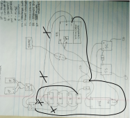
What does the relay do?I've seen this type of panel before.
I think you will find a relay behind the fuse board.
FilterGuy
Solar Engineering Consultant - EG4 and Consumers
He said that is from the disconnected charger/converter. What we don't know is wat happened to the other side.If I zoom in it appears that question mark is a red and white wire cut
John Frum
Tell me your problems
- Joined
- Nov 30, 2019
- Messages
- 15,233
Isolates the converter and the battery.What does the relay do?
The last time I saw something similar, it was in a truck camper and the rightmost positions(s) on the panel where for the propane sensor which should run all the time.
Also from memory there was no negative busbar so I assume all(most) the loads have a single positive wire and chassis return.
John Frum
Tell me your problems
- Joined
- Nov 30, 2019
- Messages
- 15,233
Actually I think it isolates most of the loads from the battery.Isolates the converter and the battery.
The last time I saw something similar, it was in a truck camper and the rightmost positions(s) on the panel where for the propane sensor which should run all the time.
Also from memory there was no negative busbar so I assume all(most) the loads have a single positive wire and chassis return.
Most of the load positions would only be energized by the converter.
FilterGuy
Solar Engineering Consultant - EG4 and Consumers
If I understand the labeling correctly, fuse positions 1-6 are only powered by the converter and 7-9 are 'always on'. A logical use for a relay would be to switch the 'always on' to the converter when it is powered and back to the battery when the converter is not powered..... but I am just speculating.Actually I think it isolates most of the loads from the battery.
Most of the load positions would only be energized by the converter.
John Frum
Tell me your problems
- Joined
- Nov 30, 2019
- Messages
- 15,233
Yes, sounds right.If I understand the labeling correctly, fuse positions 1-6 are only powered by the converter and 7-9 are 'always on'. A logical use for a relay would be to switch the 'always on' to the converter when it is powered and back to the battery when the converter is not powered..... but I am just speculating.
In the linked post 2nd picture to the right of the big transformer is the relay I mention.
Maybe @hammerhead22! 's unit has a similar relay.

HELP on wire sizes
Hi new friends. I am getting together a solar system that I will be integrating into my RV's existing electrical system. I am putting the battery, inverter, and charge controller about 12-15 feet from the DC and AC Fuse boxes from the old system. The system consists of 206Ah Sok LiFePO...
Similar threads
- Replies
- 0
- Views
- 143
- Replies
- 14
- Views
- 550
- Replies
- 9
- Views
- 444


