diy solar

diy solar

DIY 150 amps rectifier

Should I be worried about polluting the grid? I mean it's not that our government is treating us well and I have even less good words available about our grid masters.
However, I do not want to become a problem for my peers. Imagine my horror if I end up accidentally tripping the breakers.. at my neighbor's house!!!!!!
I'm bound to the same goverment and probally a differnt grid master (Amsterdam is Liander it is?)
The 150A you are talking about, is that directly from the grid or is it after a transformer? If it from the grid directly, you probably have 3 phases, that's a bit easier, but 150A you will have a special meter and you will pay alot more if you do not have "perfect" load. If you want to use it for low voltage, a switching power supply with power correction will save a lot of problems and has a higher efficiency also if you use them for your turbines the efficiency will be beter (fpc does require some frequency stability)
 
I saw your other post, now I think I know what you want to do.
You want to mak a transformer and charge your lifepo4 cells, right?
That will not work and you'll end with ruined cells. Going from AC to DC you need to take peak voltage so from 3,6VAC to DC you end up at 5V. , but the voltage on the grid will change and will reflect the output voltage. If your transformer is outputting 3.6VAC @230V, it will be 3.75VAC @240V (about 5,3VDC). For LifePo4 0,1V extra is allready a big deal, and 0,6V is the difference between optimal charge voltage and a dead battery. Also you need to limit the charge current, you can't do it like this. So if that's what you want to do, really don't do that..
 
Well, in that case. Can we just simply charge at a 3.5VDC high amp level to allow for some grid swings (there is a variac in between though)
The topping off to 3.65VDC will be done in a controlled manner using a CC/CV
 
The curent limit has to be done in almost the complete charge cycle, and in the low end SOC (where you want to use your charger) the current limit is most important.
You can have some sort of a current limit with the length of wire you are using (3.5V @140A the cable loss will have a huge impact)
But this is all theoretical, all the spices etc. on the grid will be absorbed by your battery, on a sunny day the grid can be at almost 250VAC, but in the winter it could be 210VAC in both conditions your charger should work and it should not destroy your battery.
If you would ask me, I wouldn't do it like this.
I think you are making a big battery tester here to find the limits of your battery.
If you want to make a cheap charger, I think you should try to find some Aliexpress stuff but even then you need to be very careful.
 
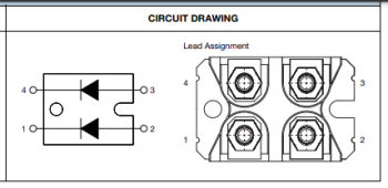
I have in the meantime gotten myself some diodes but for the life of me I do not know how to hook them up. hold on I will get the specs.


With M4 "nuts" (bolts?)
Data sheet has a diagram showing pinout and orientation of diodes.

Should I be worried about polluting the grid? I mean it's not that our government is treating us well and I have even less good words available about our grid masters.
However, I do not want to become a problem for my peers. Imagine my horror if I end up accidentally tripping the breakers.. at my neighbor's house!!!!!!

It is called "harmonics" and "power factor".
Don't worry about it. If you were a larger scale user, or if you were providing the AC from your own small inverter, it would matter more.
Power from your wind generator, it might cause some inefficiency but is simple and "we've always done it this way."

For experimenting, shouldn't be a problem. Products in Europe probably have to meet power factor requirements today.
 
We usually use a single diode as half-wave rectifier for single phase, 4 diodes full wave for single phase, 6 diodes full wave for 3-phase.
But alternatively two diodes as full wave for split phase:

 
ugg, I am a slow learner ;( Meaning that, although very informative, I did not figure out yet how to hook up my 2 diodes to form a single phase full bride rectifier.

What confuses me is why does my units have 4 terminals each?

Again, someone please draw me a crude sketch (that is applicable to the units I have). I will reward you with internet love and perhaps something more special
 
1652887514769.png

1652887580939.png

4 terminals because it contains 2 separate diodes.

To connect 2 diodes to make full-wave rectifier, you need a split-phase transformer (that is, with center tap).
Or you can use two separate transformers, primary in parallel and fed by utility, secondary in series.
 
Please stop considering this stupid and unsafe concept, it's not possible to safely construct what you have in it mind without training, well designed components, and possibility of industrial power ( 3 phase) from the utility company. Casual help from the internet won't help.
It's also possible illegal in your country as you won't just be able to connect to a power outlet.
For anyone considering giving advice just think for a moment about the possible liability issues.

Mike
 
it's not possible to safely construct what you have in it mind without training, well designed components, and possibility of industrial power ( 3 phase) from the utility company.
It's also possible illegal in your country as you won't just be able to connect to a power outlet.

"DIY 150 amps rectifier"

"Does one have suggestions on what diodes to get for a DIY single phase full bridge rectifier?"

Rectifying the output of a step-down transformer, with about 50Vrms 150A 7.5kW output?
Building a forklift battery charger?
 
Please stop considering this stupid and unsafe concept, it's not possible to safely construct what you have in it mind without training, well designed components, and possibility of industrial power ( 3 phase) from the utility company. Casual help from the internet won't help.
It's also possible illegal in your country as you won't just be able to connect to a power outlet.
For anyone considering giving advice just think for a moment about the possible liability issues.

Mike
Unless you prove this is stupid I kindly ask you to .....
 
Regarding legality, can some suggest a barrier to make it purely a private matter?

I don't have respect for our lords yet I also do not want to give them a valid reason to come busting my balls
 
"DIY 150 amps rectifier"

"Does one have suggestions on what diodes to get for a DIY single phase full bridge rectifier?"

Rectifying the output of a step-down transformer, with about 50Vrms 150A 7.5kW output?
Building a forklift battery charger?
Sorry bro, you make no sense at the moment :)
 
He appeared to say if you built a battery charger you wouldn't be allowed to plug it in.
Seems to me it is approximately a forklift battery charger. No big deal.

Backfeeding the grid with an inverter would be a big deal, and rectifying utility directly without transformer isolation would be more of a hazard (it is done inside small commercial power supplies.)
If your battery charger is meant for a 48V battery, not just individual cells around 3.5V, then voltage is high enough to present some hazard. But lithium battery at 48V is more hazardous due to current it can deliver.
 
No offence intended to anyone but this discussed method is not ideal and needs experience and skill to construct such a system safely. Even then connection an DIY experimental high current charger to a domestic supply has a risk.
If you want high current from a readily available source consider something like a ark welder for raw high current DC, or a modified server power supply for stabilised low voltage high current.

If a specification of what was required and the application for such was identified, then perhaps advice could be given that would allow progress.

Mike
 
  • Like
Reactions: PDJ
Back
Top