diy solar

diy solar

DIY 3.6kW bifacial ground mount system

Yes, there is a slope west to east and north to south, so it's done that way to be level on a horizontal plane. I think I calculated the slope at about 6-7 degrees west to east. So, it makes the east panel a couple feet higher than the west one. I didn't do it that way to get more west sun, it just worked out that way. The array is oriented almost due south. An added benefit is since the array is higher on that end, it ought to catch more sun early in the morning on the back side cells in the summer months.
I'm assuming there's a site or calculator that helps one figure this out? I've paid so much attention to the electrical side and haven't really got into the panel side yet. I am also looking to use santan solar for used panels or new ones if the price is right.
 
I'm assuming there's a site or calculator that helps one figure this out?
Not sure what you're asking. The angle comes from me running a mason, or plumb line across the back post line, and then from the back to front posts, and using a line level. The angle came from doing some trigonometric calculations.

To get the south orientation set up, I just set up a couple posts in a general south direction and waited for the sun to get to solar noon. If the post shadows line up at that time then they're probably lined up to due south. But, I think it ended up being oriented about 178 degrees, but that was close enough.
Oh, ok..installers use calculations based on regions to be precise. I just counldn't remember the site and tools they used.
 
Ok, here it is, just put in your latitude and it will give you your ideal fixed angle, plus there are other calcs, like 4 seasonal angles if your array is adjustable. @Steve777 gave me the info on it, and has been really generous and helpful with his knowledge on this subject. I am very grateful for the help and advise he has offered me.

 
Also, I'm curious of what the downsides are to using wood to build the panel/s support framework as oppose to using a metal racking system? Good pressure treated wood should last a few decades ...right?
Sorry, didn't see this part until now. I'd actually prefer metal, but finding the appropriate metal tubing was difficult and more expensive. So I went with treated wood as the lumber was easier to obtain. But cheaper? It's hard to say, I spent about $750 on this ground mount. This includes the lumber (mostly 4x4x8's, some 4x4x6's and 2x4x10's), unistruts ($40 apiece for each 10ft rail, I used 6 of them), lots of hardware, and quikrete (20 50lb bags).

Some downsides of wood are that it can shrink and expand according to its environment, which could stress the panels. As far as longevity goes, it ought to last at least 10-15 years, if it's taken care of. I put the posts in quikrete, but put gravel at the bottom of the post hole before the post was put in. This is to facilitate water drainage and avoid direct soil contact. I also used cut angled sonotubes on the top of the hole around the post to keep water from pooling at the base of the post where it meets the concrete. And I stained the posts after they were installed to prevent any water degradation. Will it last? I guess we'll see. I will say it seems very sturdy, we've had a couple days of wind gusts around 60mph, and I couldn't detect any movement.
 
Last edited:
What kind of inverter do you have and what do you think of its performance? I have an EG4 6500EX, and it seems to work just fine for me. But it's not been put in full time operation yet either, even tho I've run about 50kwh thru it.

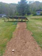
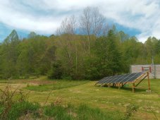
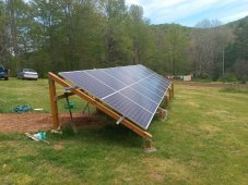
Edit- I just saw your tagline showing you're using two LV6048's. But I'm still interested to see how they've done for you. Also you have adjustable solar arrays? Do you have any pics of this?
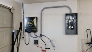
Yes I picked the MPP 6048's (over the more popular 6548's) both actully output the same total at 6500W per unit, but the 6048 is designed to output 120 and 240 in a single AIO unit, where the 6548's take two units to do this. This allowed me to start with just one inverter and still have 120/240 output, and now that I have two, if one failed I could reset the other to single unit operation and keep running 120/240 just at half the total output.
The cost was higher standby consumption. Each 6048 if you open one up, is actually two inverters inside of 3.25kW each, and so each is also consuming energy to run, even in standby. I knew that going in, and allowed some extra PV panels. This works 'most of the time' but not in November so much, as that is my worst month (cloudy short days). I am happy with these units and am considering a third one, which could be just a spare, or could increase my output to 18kW if I need.
As to the tilt:
If you don't get snow then my advice is don't bother with a tilting array.
Go to PVwatts and input all the info for your location and PV total kW, and orientation (ie "south" =180 degrees) then start with a tilt angle that matches your latitude as a starting point, and play with lower angles or higher angles and see what you get. In the advanced settings you can even select bifacial panels (as I have) and other features to improve the calculator.
I made a chart of what angle was 'ideal' for each month of the year for my orignal 7.04 PV array, and totalled up the annual kWh predicted by PVWatts.
Then I played with single angles for the whole array and found what single angle would give me the best annual kWh without any tilting and this angle was a bit lower than my latitude. The difference is not very impressive really, IIRC the spread was only about 10% or so over the whole year, BUT looking at where this difference was mostly coming from, I could see the Nov-Dec-Jan period would do much better with a steep angle (60-72 degrees) AND where I live this also helps remove most of the snow.
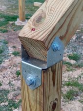
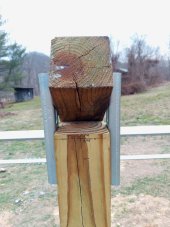
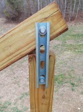
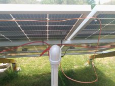
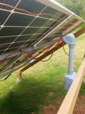
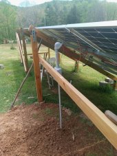
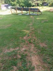
So the extra work, cost and effort to operate the tilting was justified (for me) by better snow clearing, and better energy collection during the worst months of the year. I will try to get a couple of pics of how the tilt works.
 
Go to PVwatts and input all the info for your location and PV total kW, and orientation (ie "south" =180 degrees) then start with a tilt angle that matches your latitude as a starting point, and play with lower angles or higher angles and see what you get. In the advanced settings you can even select bifacial panels (as I have) and other features to improve the calculator.
Thanks for the explanation. I actually have gone to the PVwatts site, to see if an adjustable array would be worth it. I punched in a 4.5kw array, at due south, and played with the angles from 10 to 60 degrees in 10 degree increments. I then took the best output for each month and added them together, which came out to about 6.32mwh per year. Set at the ideal angle for me, which is 32 degrees, the annual total was about 6.02mwh.

So, having an adjustable array would gain me about 5% more power. Not worth the trouble in my location. But, it probably does matter for someone further north, especially in the winter.

And yes, snow is not an issue here, we rarely get more than a half foot of snow. And even if we did the snow could be easily removed.
 
Not worth the trouble in my location.
Exactly!
I can tell you, there is a Government Funded (huge) PV array not too far from my area, built fixed on a roof assembly at about 30-degrees from horizontal, and it was buried in snow most of the winter, while my tilted arrays at 60-degrees from horizontal were clear all winter. For people who have to deal with snow, this is a huge difference.
 
My idea of the adjustable array was this:

If you seen my pics, the front of the 4x4 posts that support the rails, I used 1.5in lag screws to fix them to a top clamp. Where the back of this post meets the back posts I used two mini struts on either side, also using 1.5in long lag screws. (See attached pics).

So to make them adjustable, I would run a 4in bolt thru the front of the post as a pivot point. On the back of the post, I'd run about a 5-6in bolt thru the post horizontally. The back vertical post would also get another similar bolt. Then I'd use a top link, like you see on the back of a tractor, which can be adjusted in length. On one side, the bolts would be fit thru the holes of the top link. On the other side would be a metal plate with holes drilled in it in predetermined locations.This would add support to the top link.

So to adjust the angle, the support plate would be loosened, and the top link could be adjusted by turning it in whatever direction.

Kinda mad scientist stuff, but in the end, I just wanted to get it done. So I just set it and forget it.
 

Attachments

  • 20230215_173807.jpg
    20230215_173807.jpg
    238.6 KB · Views: 10
  • 20230214_135059.jpg
    20230214_135059.jpg
    150.9 KB · Views: 10
  • 20230214_133455.jpg
    20230214_133455.jpg
    192.2 KB · Views: 10
Been digging the PV trench the last couple days, it's a chore, have to go 45ft between the array and the house. Started by using a tiller to tear up the topsoil, then have been using a pickaxe to dig the trench.

Later this afternoon I was digging down near the array and had to stop it’s about to start raining. Also was digging down near the array and hit a solid object. At first thought it was a big rock, but turned out to be something else.

Turned out to be the concrete lid to the septic distribution block. We asked our plumber nephew to come over and he identified it. So I’ll have to figure a way to go around it.

Back in November when I was digging post holes for the rear posts, I hit a 4in green sewer line. We thought it may have been a older cistern line, but guess it’s one of the outlet lines from this d-box. Or maybe it should be called the shi* d-box. Figures. We thought this would be further away than it is, but apparently not.

Some pics of the trench and said d-box. Trench is 45ft long, I ripped up the topsoil with the tiller, then started digging the trench with a pickaxe. It’s about a foot deep now, another 8-10" to go. Maybe I'll just go a foot deep, I'm not having it inspected anyway. There's no traffic in this part of the yard other than the riding mower.
 

Attachments

  • 20230414_173946.jpg
    20230414_173946.jpg
    357.3 KB · Views: 19
  • 20230414_124246.jpg
    20230414_124246.jpg
    297.6 KB · Views: 16
  • 20230414_124202.jpg
    20230414_124202.jpg
    339.5 KB · Views: 19
  • 20230414_174015.jpg
    20230414_174015.jpg
    350.1 KB · Views: 18
Finished up with this project yesterday. Over the last few weeks, I dug out the PV trench down to 18in. Laid conduit about 10 days ago from array to house, used just about all of six 10ft half inch pipes in the process. Also for grounding the array, I ran a bare 6awg wire between the panel frames and rails, using a lug that bit into the metal and to make electrical contact.

I had to run three solid 10awg wires thru the conduit which was a no-go the first attempt. Tried again with lube, nope. I was about to re-run it with 12awg, but thought why not tape the wires together before I pushed them into the pipe, that would minimize any possible tangling of the wires which prevented any progress. So, I straightened out and laid out about 60ft of three wires down the length of the house and slowly taped them into a tight bundle every 8-12in as I pushed them into the conduit. It took about 3+ hours but I was able to push just about all the wire thru where it then stopped. So I went down to the array and was able to pull the final 10ft out. Yay! That was on Wed..

On Thursday I installed a junction box at the array, tied off the PV wires to the array rails and ran them and the grounding wire through a weather head into the junction box. Then I went back inside and mounted the IMO disconnect on the wall and hooked up all the PV and ground wires. After I joined the PV and ground wires to the THWN wires in the box, I buttoned it up and turned everything back on about 7pm, and it's been running since then. Yesterday I filled in the trench the best I could, so I can say this project is done.

For now.
Until I get some batteries.
And some more panels.

Thanks to those of y'all on here who helped me along the way, especially @Hedges, @FilterGuy, @timselectric, @Adam De Lay and the many others on here who offered me their invaluable advice. I'm sure I'll be picking your brains again soon enough. I'll post some more pics soon.
 
Last edited:
Some pics of the finished product, and some views of the farm on a beautiful spring day.
 

Attachments

  • 20230508_124612.jpg
    20230508_124612.jpg
    306 KB · Views: 46
  • 20230508_124306.jpg
    20230508_124306.jpg
    291.4 KB · Views: 47
  • 20230508_124758.jpg
    20230508_124758.jpg
    344.9 KB · Views: 54
  • 20230508_124409.jpg
    20230508_124409.jpg
    259.7 KB · Views: 53
  • 20230508_124231.jpg
    20230508_124231.jpg
    271.7 KB · Views: 52
  • 20230508_123916.jpg
    20230508_123916.jpg
    427.1 KB · Views: 54
  • 20230508_124544.jpg
    20230508_124544.jpg
    517.7 KB · Views: 51
This is such a cool well documented DIY journey...fantastic photos & awesome detailed write-up. Well done...thx for taking the time.
Thanks, I appreciate it. There was a lot of planning, sketches, calculations, etc. You should see my notebook, I bet it's got 25 pages of drawings, calcs, parts and price lists and so on. I like to document things as I go. It's a bit mad scientist kind of stuff, but I'm weird that way. My wife is on board with it somewhat, but when I start talking about the details of things, big question marks form over her head, and she starts to tune out. But that's okay.

Hopefully this thread isn't at its end, but just the beginning. I look forward to seeing how your project goes as well.
 
Well, the system has been online for over three months, still no batteries installed, but it has generated about 325kWh of
solar power total. No issues really with the system, altho there has been a few glitches, where the inverter has shut off for less than a
second. But those have been very rare, and haven't had any over the last month or so. The trench I dug for the PV wires has almost totally
filled back in with grass after it was backfilled around the first of May. So the obvious gash in the yard is slowly healing over.

The savings in our electric bill has been about 10%, or $10-12 per month. With the system running, we save about 100kWh per billing period, which is about 31 days. We'd probably save more if it wasn't for outrageous "environmental" and "fuel adjustment" surcharges, which tack on another 25-30% to our basic bill. Guess that's the cost of fewer power generating plants, or the cost of using less "environmentally unfriendly" fuels, i.e. coal. So, the savings on our bill aren't a lot, but like I've said in the past, I don't really care about it paying itself off.
 
And finally last weekend my wife and I installed the panels. They were hefty, about 63lb apiece, and were stored in our old house about 75 yards from the array, so it was a chore getting them up to the site and then mounting them. She held them roughly in place while I fastened them onto the struts. I added 10ft 2x4's on the tallest of the back posts to give it more lateral stability. I plan on adding some from the front to back posts as well. It's pretty stout and stable as is.
I recently bought 400 watt bifacials from SanTan also. I mounted them on my patio cover. Before I mounted them, I applied a white roofing coating to get as much as I could from the bifacials. You might think about putting a layer of white rock under your panels. It would also make it so that you wouldn't have to mow under them. Just an idea.
 
Some pics of my progress.

Pic 1, inverter hung with conduit installed. Output goes to sub panel seen in Pic 2.
Pic 2, 12/24 sub panel. Will transfer critical loads to it soon from house panel, via hole in wall above house panel seen to the right. I opened up a 1.5 inch knock out on the top of that panel, and will run the wires through a 90 degrees elbow and thru flex pipe into the top right of the sub.
Pic 3, view of conduit (1") running under house between inverter and sub panel.
Pic 4, view of conduit (1”) coming thru trench up into pole service panel where 60A DP breaker is installed to provide grid power to inverter.
Pic 5 and 6, view of input conduit trench from where it goes up into the house. Curve happened because I had to work my way around buried ground rod which was in the way. I ran about 9ft of straight conduit up to where it starts to curve back left. So I used a 45 degree elbow to get it around the corner, then a 90 degree elbow up to the panel. Was a difficult wire pull with two 4 gauge and an 8 gauge wires. Had to retape it so it was more streamlined in the pipe.
I have exactly the same setup: one eg4 6500, main breaker that I moved the circuits to a sub panel, one eg4 batter. I have power from into the inverter from the main breaker panel and power out from the inverter to the sub panel (which has ground and neutral separated). All working wonderfully.

Question... How did you setup your grounds. I ran a ground wire from my main breaker panel (which has the ground and neutral bond already) to the eg4 inverter line "in" ground, then I ran a ground from my sub panel to the main breaker panel. Is this correct?
 

Attachments

  • 20230612_184727.jpg
    20230612_184727.jpg
    186.7 KB · Views: 10
I have exactly the same setup: one eg4 6500, main breaker that I moved the circuits to a sub panel, one eg4 batter. I have power from into the inverter from the main breaker panel and power out from the inverter to the sub panel (which has ground and neutral separated). All working wonderfully.

Question... How did you setup your grounds. I ran a ground wire from my main breaker panel (which has the ground and neutral bond already) to the eg4 inverter line "in" ground, then I ran a ground from my sub panel to the main breaker panel. Is this correct?
Nice, looks like your garage? Since we don't have a garage, I cleared out part of my clothes closet. It's a bit noisy, even when it's in bypass mode, but it's tolerable.

Regarding grounds, I ran a 8ga ground wire from the service pole panel where the ground and neutral are bonded. I ran that ground wire and a 4ga hot and neutral wire to the inverter's AC input. From the inverter AC output to the critical loads subpanel, I ran a 4ga hot and neutral, but not a ground wire. In hindsight, I probably would've run that ground wire. I did run a ground wire from the subpanel to the house sub panel, which has all the home circuits on it. That panel does not have the N/G bonded. There has been a lot of discussions about how to wire the grounds for this particular inverter on the forum, but I believe the consensus was to run a ground wire from the inverter output to such a subpanel. I do not have the ground and neutral bonded on this panel.

Saying that, if I do have a ground fault though, it should clear it okay whether in bypass or inverter mode (I only have solar panels, no battery yet). In AC bypass mode, it's pretty straightforward; in inverter mode, it's a bit convoluted, but it should still clear the fault.

@Hedges and @FilterGuy could explain it better than me. And there's the issue of the N/G bond in this inverter. My inverter was shipped with the N/G bond screw, and I did not remove it. Because of that, I moved my critical load hots and neutrals to its subpanel. Earlier this year, Sig Solar started shipping these inverters without the N/G bonding screw, and has updated the firmware to deal with this change. I chose not to remove the N/G screw and have not updated the firmware. It's confusing enough as it is for me, so I chose not to update anything. I haven't had any issues the way it set up, and it's been running just over 3 months. There are threads dealing with this issue in the forum, and Sig Solar has issued a video on YouTube regarding this.
 
Last edited:
Back
Top