diy solar

diy solar

DIY All-In-One Solar Generator - Control Board

True, it was Cal's slip I caught:


I think my professors hated me.
Major government contractors who's work I reviewed certainly did! :)

Now I'm confused. It doesn't appear that the circuit works. The zener anode and cap should be connected to PV ground. U1-4 should be connected to zener cathode to supply 12V to the gates.

The time constant is 2.2 sec when U1 is off.

Actually, time constant is yet higher than 2.2 sec since the zener will rob cap charging current.

Edit, my error. That's how the circuit is implemented. There's just a "dot" connection missing on the schematic which threw me off.

U1 can not be activated until the cap is fully charged. The 10k resistor in NOT in the circuit at this time. The time constant remains as I stated.
 
Last edited:
Now I'm confused. It doesn't appear that the circuit works. The zener anode and cap should be connected to PV ground. U1-4 should be connected to zener cathode to supply 12V to the gates.

The time constant is 2.2 sec when U1 is off.

Actually, time constant is yet higher than 2.2 sec since the zener will rob cap charging current.

You're right about RC time constant, my eyes were blurry this morning.
The 10k isn't in the circuit making a divider until the BJT turns on.
Prior to that, time-constant for C1 rising towards 1/e of 47V is 2.2 seconds.
But it only rises 1/4 of the way to 12V before zener clamps that. Takes what, 1/4 of a second?

For a diode in the forward conducting direction, "current" (opposite of electrons) flows from positive supply to negative in the direction of the triangle "arrow" in the symbol, correct? So the Zener is reverse-biased, draws little to no current until voltage approaches the 12V knee. It doesn't affect RC time constant until then.

Oh! missing the dot! Neither the zeners nor the capacitor do anything at all as drawn. Bhupinder - avoid a cross for connection in schematics, use a "T" so unconnected crossings are clearly different from connections:
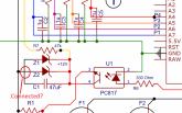
1598283650231.png

In an earlier incarnation, the zeners were connected correctly but the capacitor was not:
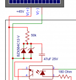
1598284206962.png

There's a danger in re-drawing circuits. Best to create a netlist and compare old & new schematics.
I've made that mistake and produced broken designs, either renaming a net on one page but not another, or rearranging and causing wires to connect, then separating them again but incorrectly. Ended up with + and - inputs to an op-amp reversed, had to lift leads of an SOIC to rewire.

Below the ideal bias current the zener still conducts, just less. So with the resistors selected it'll be a bit below 12V, loosely regulated. I think it still works.

Other than the missing connection (and divider networks so microprocessor ADC can measure Vpv), I think the circuit works.
 
Last edited:
The design can be made significantly simpler. Ditch the low side switch and use relays. That's what I'm using to disconnect solar.

I have an automotive 30A relay configured in the normally closed contact position. This relay doesn't consume any power during normal operation. During overvoltage conditions a second relay is energized, which then power the 30A relay and opens the NC contacts. The smaller relay consumes 1.7 mA current. Total current consumption under normal conditions is only 1.7 mA, significantly less than using the low side fet switch.

Edit, actually just require the 30A relay and supply a 12V signal to the relay coil for overvoltage. There's zero power consumption during normal operation.
 
Last edited:
However, with differential P/N inputs, I think the variation input is cancelled. So long as leakage current is the same for both inputs (probably varies as a function of input voltage), and resistor network impedances are the same.

The common mode one will be (assuming both inputs have the same leakage characteristics, not sure they have tho) but the differential one will not. The best we can hope is that it's more or less linear and proportionnal to the voltage and/or a simple offset as that can be compensated with calibration in software.

But it's easy to avoid most of it anyway: just divide all the resistors values by 5 or 10 and the input leakage error will be divided by the same ratio. The impedance is still high enough to not draw too much current.

True, it was Cal's slip I caught:

I think my professors hated me.
Major government contractors who's work I reviewed certainly did! :)

No worries ;)

The spec'd test current for a 12V zener (1N4742A) is 21 mA.

Bias resistor for one diode is : 37V - 12V / 21 mA = 1.2 k ohms

Since OP wants two parallel diodes, bias resistor should be 600 ohms. I wouldn't recommend that. Better to use the 1.2 k ohm resistor and just reduce bias current to about 10 mA each.

Yea but we don't need to have 12 V exactly here, as long as we are in the knee enough to have decent regulation it'll be fine.

I think a 15k resistor will not provide adequate bias current. 37V - 12V / 15k = 1.7 mA
That's 0.9 mA per diode. That could be below the zener knee.

It was just a rapid guess, precise value calculation is left to the reader :D

An isolated dc/dc converter, powered by the battery would be a better choice. The converter probably uses less current than the zener bias current.

That's exactly what I have proposed right at the start actually... but he didn't want that as he couldn't obtain one easily. They tend to have a pretty high Iq so current consumption would be roughly the same as the zeners.

Oh! missing the dot! Neither the zeners nor the capacitor do anything at all as drawn. Bhupinder - avoid a cross for connection in schematics, use a "T" so unconnected crossings are clearly different from connections:

Yeah I don't know what EDA software he uses but it allows a lot of things proper ones would not allow, making the schematic clearer right from the start.

The design can be made significantly simpler. Ditch the low side switch and use relays. That's what I'm using to disconnect solar.

Yep, but relays eats larger amount of power. Problem you can solve like this:
I have an automotive 30A relay configured in the normally closed contact position. This relay doesn't consume any power during normal operation. During overvoltage conditions a second relay is energized, which then power the 30A relay and opens the NC contacts. The smaller relay consumes 1.7 mA current. Total current consumption under normal conditions is only 1.7 mA, significantly less than using the low side fet switch.

but then it's a lot less safe as the default mode of the circuit is not in protection (same as using a NO contact for an e-stop; it's far better to use a NC one so if a wire gets cut or disconnected you just have a nuisance trip instead of a non-functioning e-stop...).
 
Last edited:
The design can be made significantly simpler. Ditch the low side switch and use relays. That's what I'm using to disconnect solar.

I have an automotive 30A relay configured in the normally closed contact position. This relay doesn't consume any power during normal operation. During overvoltage conditions a second relay is energized, which then power the 30A relay and opens the NC contacts. The smaller relay consumes 1.7 mA current. Total current consumption under normal conditions is only 1.7 mA, significantly less than using the low side fet switch.

Edit, actually just require the 30A relay and supply a 12V signal to the relay coil for overvoltage. There's zero power consumption during normal operation.

By automotive relay, do you mean rated 12VDC? Should work for opening under no-load but could be a problem opening under load to PV voltages. Or is it just meant to disconnect array in the case of high Voc under cold conditions?

As a child I learned that capacitors help switches interrupt DC (from ignition systems.) I used that with a household circuit breaker in a 12V battery bike motor circuit. I've since learned how to engineer snubbers. Series RC might be good for your relay.

The manual for my Sunny Island Charger recommends a relay to disconnect battery using it's output signal for battery over-voltage (I suppose it latches on, since it can't see battery after that). I think it is shorted FETs in the switcher or perhaps other controller malfunction they're concerned with, so it doesn't cook batteries.
 
Below the ideal bias current the zener still conducts, just less. So with the resistors selected it'll be a bit below 12V, loosely regulated. I think it still works.

Other than the missing connection (and divider networks so microprocessor ADC can measure Vpv), I think the circuit works.

Zener regulation is a critical circuit. I would not go below 2 mA . Using two zeners adds to the problem. Get rid of one of the zeners.

R7 = 37V - 12V / 2 mA = 12.5k

Rather than having the microprocessor ADC monitor Vpv, have it monitor Vz. That's the critical voltage for activating the fets. It needs to be stable.

But wait, it's not possible to monitor either voltage since the grounds are not connect yet! The processor is in the dark.

So just monitor Vpv, when high enough you know Vz is too. Don't need ground connected to do that.
My suggestion, which isn't in the circuit yet, is 100k + 100k divider between processor VCC and GND, setting 2.5V input into ADC. Two of these, one with 2 Meg to negative PV, the other with 2 Meg to positive PV. Now you don't need a solid ground reference, just requires negative PV and positive PV to both be within +/-100V of microprocessor. That way, doesn't matter if either is open circuit or if either has some connection or leakage path to battery. The differential PV positive/negative voltage is presented as differential input to microprocessor, staying between zero and 5V.

Zener - I wouldn't worry about it. Didn't find curves for his part number, but here's another with Iz vs. Vz. Voltage regulation is reasonably sharp whether at 10 mA or fraction of a mA

 
By automotive relay, do you mean rated 12VDC? Should work for opening under no-load but could be a problem opening under load to PV voltages. Or is it just meant to disconnect array in the case of high Voc under cold conditions?

As a child I learned that capacitors help switches interrupt DC (from ignition systems.) I used that with a household circuit breaker in a 12V battery bike motor circuit. I've since learned how to engineer snubbers. Series RC might be good for your relay.

The manual for my Sunny Island Charger recommends a relay to disconnect battery using it's output signal for battery over-voltage (I suppose it latches on, since it can't see battery after that). I think it is shorted FETs in the switcher or perhaps other controller malfunction they're concerned with, so it doesn't cook batteries.

That's right, in the old days when the distributor capacitor fails, the the points quickly pit and fail. That left me stranded once.

RC snubbers are good for for relay contacts. I fixed a run-away machine gun with a snubber circuit many years ago. The relay contacts got so hot they melt together. In my case, I only have 130W solar with currents around 6.5A. Don't think I need spark suppression. The relay is the primary disconnect for the 130W panel in case of battery "overvoltage" or cold conditions.

Granted, it's customary to mechanize the relay to a fail safe position. My disconnect relay is not fail safe. As mentioned, if the relay coil wire is severed then the relay is useless and will not disconnect solar. That's ok, the SCC is setup to limit charging below the absolute max battery voltage. The SCC is the secondary safety valve. The BMS has a beeper and it will notify me if the relay doesn't disconnect.
 
Zener - I wouldn't worry about it. Didn't find curves for his part number, but here's another with Iz vs. Vz. Voltage regulation is reasonably sharp whether at 10 mA or fraction of a mA


That's not how I see it.

Look at the differential resistance spec. At 1 mA, the 12V zener has 150 ohm resistance. At 5 mA, the diode has 10 ohm max resistance. Voltage regulation at 1 mA is clearly at the lower section of the curve. I don't believe you can predict voltage at a fraction of a mA.
 
That's not how I see it.

Look at the differential resistance spec. At 1 mA, the 12V zener has 150 ohm resistance. At 5 mA, the diode has 10 ohm max resistance. Voltage regulation at 1 mA is clearly at the lower section of the curve. I don't believe you can predict voltage at a fraction of a mA.

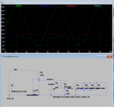
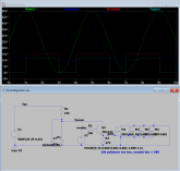
I tried the regulator circuit in LTSpice with a couple substitutions using whatever was in the library.
Main problem I see is that 47k & 10k can't be at 12V unless Vpv > 68V
Using 47k pulldown seems to work. I does have a 5 ms time constant to turn off gate. Just so long as MOSFET has enough thermal mass to soak of the power dissipated in that time.


1598333329179.png

1598333504498.png
 
Yeah, the circuit is all screwed up. In this case, since the zener diode doesn't zener, you just got a voltage divider between R7 and R1.

The "zener regulated voltage" (which is also the fet gate voltage) drops to:

Vg = 35V * 10k/(47k + 10k) = 6.1V

The OP could be looking at a major disaster when on a cloudy day Vmp drops below 35V.

The correct way to design the zener circuit is for the bias resistor to account for the load current. Steady state load current is 12V/10k = 1.2 mA.
We'll include a buffer and say load current is 2 mA. Estimate min zener current at 5 mA. Not sure what the minimum Vmp can get down to? Estamate Vmp_min = 30V.

R7 = Vmp_min /( Iz_min + I_load)
R7 = 30V / (5 mA + 2 mA) = 4.2 k ohm

In addition, the second zener diode should be removed.

An isolated dc/dc is looking better and better. Or a high-side switch. No problems with a high side switch.
 
Last edited:
Switchers are a lot of technology, running constantly and optimized for cost not necessarily 10+ year life.
High-side switch you still need to switch fast enough in both directions (and regulator for gate voltage). Although power dissipation during transition is not a big issue because only an occasional switch, not many Hz as used in a switching power supply.
I could replace the 10k pulldown with an active inverter circuit made from 2N2222 for faster switching and lower quiescent power draw. Then a low current zener regulator and the decoupling cap would supply all that's needed. Should still have a weak resistor hold-down of gate for when active clamp is inactive due to low PV/regulated voltage.

I used to design state of the art microprocessors. And write CAD tools (Cadence didn't exist). But if I can make something work with static analog logic, I do.

Don't understand, why do you require a regulator for gate voltage when using a high side switch?

Instead of fan, insert SCC. Instead of 12V, insert PV+.

dXOJT.png
 
Don't understand, why do you require a regulator for gate voltage when using a high side switch?

Instead of fan, insert SCC. Instead of 12V, insert PV+.

"Instead of 12V, insert PV+" is why. PV+ = 45V, Vgs(max) of MOSFET is 20V. So it needs at least a voltage divider to regulate it. I'd use a zener, and the circuit would be good for a wider range of voltage.
 
  • Like
Reactions: Cal
Yes, circuit needs a resistor connected to the collector of Q3 in order to add a voltage divider. Still a very simple circuit. It eliminates the isolators used in the low side switch as well as the "funky" gate drive circuit.
 
I have to ask. What is your objective here? Are you trying to learn how to do this or are you trying to save money?

If you think you can save money this way, you are hopelessly deluded. If you want to understand how to design high power circuitry that has life safety implications, then I recommend you take a couple of electrical engineering classes. DC circuits, AC circuits and elertronic components should do the job.

Then look at reference designs from component vendors. Once you understand how the reference designs work you can start designing your own.

Generally I would be fine with stumbling around as a way to explore stuff you don't understand, but this stuff will kill somebody if you get it wrong.
 
I have to ask. What is your objective here? Are you trying to learn how to do this or are you trying to save money?

If you think you can save money this way, you are hopelessly deluded.
Not So much, just the component costs have exceeded that of a decent BMS.

If you want to understand how to design high power circuitry that has life safety implications,....
May be Yes.

I recommend you take a couple of electrical engineering classes. DC circuits, AC circuits and elertronic components should do the job.
How do you suggest to go about it? Enroll @ University?
If not - what did you make out of things we are trying to do here?

Then look at reference designs from component vendors. Once you understand how the reference designs work you can start designing your own.
No, I don't intend to write my thesis around physics behind functional principals of electronic component and their comparative studies.

Generally I would be fine with stumbling around as a way to explore stuff you don't understand, but this stuff will kill somebody if you get it wrong.
How exactly? Sorry, but I fail to understand the process whereby a PCB turns itself into an automatic loading and targeting weapon that could kill anyone in straight line of sight?

Come'on we're trying to do a harmless design with some small electronics components learning how they work in the process.
It's no one's job to come and dump their heavy opinions around. Sorry - not welcome!
 
Last edited:
How do you suggest to go about it? Enroll @ University?

How exactly? Sorry, but I fail to understand the process whereby a PCB turns itself into an automatic loading and targeting weapon that could kill anyone in straight line of sight?

Look up MIT Open Courseware.
They've recorded lectures, made assignments and tests available, all free on the web. You can purchase the older edition textbooks listed cheap on Amazon. For practically nothing you can get the same education that would have cost $20,000 per year if you were even admitted, and not cut from the program in subsequent screening (as is done for their advanced degree programs.)

The voltages you're dealing with are just low enough that they are generally considered safe. So long as you are bone dry, not standing in a puddle when you grab a wire. The power from a single PV panel is below the threshold where code now requires isolation in the event arc-faults occur. It could be used to start a fire, but you would have to try a bit harder to accomplish that.

Most of us are dealing with voltages and/or currents that could cause series damage. Like PV Voc around 480 VDC, 240 VAC from the grid with arc-flash potential, and battery banks capable of delivering several thousand amps (one loose connection could melt copper or steel.)
Thanks @Hedges . That's the reason I opted for a 12V "Safe" portable system. No direct interference with line AC as well.
I believe we are playing with a very basic and safe system - which @ max could smoke black with a "Pop" sound from some cap - nothing more.
I don't know, I'm not fan of formal classroom education anyways nor am I planning to be a circuit designer in foreseeable future so those classes are not why I came to the forum. But Yes, they could be a good reference to anyone willing.....thanks for sharing though.
BMS no problem. AC inverter is the part I would be leery of.
 
Back
Top