diy solar

diy solar

Do I have a ground fault situation?

sidtupper

New Member
Joined
May 18, 2021
Messages
10
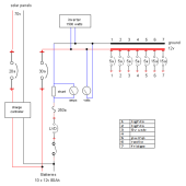
A couple of days ago, after years of problem-free operation, my power distribution circuits went crazy. Here is the layout:
1682961647330.png

I ran a vacuum cleaner off the inverter, something I've done many times before without issues, and after a minute or two it stopped. The charge controller displayed 13.8v battery voltage but the voltage across the breaker bus went down to 6v. The Low Voltage Disconnect didn't activate. I set all of the breakers to OFF and the voltage there returned to 13.8v. If I turned any of them ON, with nothing active on the circuit, eg, no lights switched on, the breaker bus voltage dropped 1 - 2 volts. I measure 1.25v from negative to earth.

Does this mean I have a ground fault? How do you locate ground faults?
 
It means you have a fault.
And it could be the 30A fuse you show on the way to the inverter blew but is arced. A 1500W inverter needs a 125A fuse, minimum.

The drawdown to 6V though… does the inverter power on?
What gage cables to the inverter from batteries? Are the cables crush-crimped or crimped properly with a hex swage crimper?
If I turned any of them ON, with nothing active on the circuit, eg, no lights switched on, the breaker bus voltage dropped 1 - 2 volts
Does the inverter turn on with all the 12VDC circuits turned off?
 
Ditto; not a ground fault. There is some resistance in the circuit somewhere. If you have 6V on the bus, the other 6-7V will be dropped across the bad point, breaker, fuse, switch. Check the voltage across each device.

Also, your shunt won't be measuring the solar to the battery.
 
Ditto; not a ground fault. There is some resistance in the circuit somewhere. If you have 6V on the bus, the other 6-7V will be dropped across the bad point, breaker, fuse, switch. Check the voltage across each device.

Also, your shunt won't be measuring the solar to the battery.
Thanks! I’ll get right onto this.
 
It means you have a fault.
And it could be the 30A fuse you show on the way to the inverter blew but is arced. A 1500W inverter needs a 125A fuse, minimum.

The drawdown to 6V though… does the inverter power on?
What gage cables to the inverter from batteries? Are the cables crush-crimped or crimped properly with a hex swage crimper?

Does the inverter turn on with all the 12VDC circuits turned off?
Thanks for responding. I will upgrade the 30A circuit breaker to 125A. The inverter doesn’t power on, even with all of the 12v circuits off; it indicates low battery voltage. The cables to the inverter are like jumper cables, really thick, 1/4” copper stranded, with soldered connectors.
 
The cables to the inverter are like jumper cables, really thick, 1/4” copper stranded, with soldered connectors.
One of those soldered joint’s probably failed due to the jumper cables being way too small of a wire gauge. 1/4” is too small for that and it probably got hot and melted something somewhere from the current.

Look at the chart on this page. It would appear that 2ga is adequate but I would use 1ga minimum (my 1200W and 2000W are both 2/0 fwiw).
I do not solder many things because that hasn’t provided the best longevity with vehicle battery cables so I’m even less inclined to use soldered wire in my house. Use a good solid crimp connection so that temperature failure cannot occur.
will upgrade the 30A circuit breaker to 125A.
How it ran at all is beyond me.
I would think that your system as drawn would have blown the 30A fuse faster than a July 4th display of civil affection.

But seriously: the jumper cables are likely way undersized and not insulated for continuous power.
 
I took the inverter out of the system until I can install a 200a breaker, and then I’ll reconnect it with short fat cables directly to the batteries, no LVD or shunt since I only use it briefly to grind coffee, etc., and mostly have it turned off. No sign of melted solder. No improvement either … still get voltage drops on some (not all) circuits.

For example, one circuit just supplies 12v to two reading lamps in parallel, and when I turn that breaker on, with the lamps off, the voltage across the breaker is zero but the voltage to ground drops a couple of volts. I don’t see where the drop happens. Maybe the lamps aren’t really off?

I see the same thing happening on a circuit that just supplies some usb power sources. A clamp ammeter shows about 0.5a on these circuits but I don’t trust it because it shows non-zero clamped on nothing. I’m sure I’m missing something that’s staring me in the face.
 
Don’t just focus on + to -
Voltage doesn’t need polar opposite potentials just a difference in potential.

I’d carefully do voltage drops on the main wiring to the fuse box
 
Start with this part of the video, it shows how to perform a voltage drop test. This is the proper way.


Start at the battery end of the circuit, then measure the voltage drop, which is the difference in voltage potential, between two points in a circuit. When you see a higher value when measuring between two points, that means there is higher resistance. In your case, I'd look for any voltage drop over 0.5V.

It is important to remember that all voltage drop testing needs to be done with a load on the circuit. It can be a headlamp bulb for example.

I use voltage drop testing almost daily. Once you understand how it is done and why, you will use it any time you need to find faults in a circuit.
 
Sorry, but what kind of battery? Is it EOL AGM? A large load like the vacuum could have been the straw that broke the camel's back.
 
Thank you for the comments to my plea for help post, which led me to the root of the problem … the culprit voltage drop was in the Low Voltage Disconnect which blew up, I guess, when its 30a spec couldn’t handle the inverter’s vacuum cleaner load. I’ve since moved the inverter to its own circuit, with a 200a circuit breaker.
 
Thank you for the comments to my plea for help post, which led me to the root of the problem … the culprit voltage drop was in the Low Voltage Disconnect which blew up, I guess, when its 30a spec couldn’t handle the inverter’s vacuum cleaner load. I’ve since moved the inverter to its own circuit, with a 200a circuit breaker.
You might want to invest in an infrared thermometer. Under load, when a connection is less than optimal, a "bad" connection, or undersized conductor can be seen as heat.
 
Back
Top