diy solar

diy solar

EG4 18kPV Q+A general thread

There are new and improved firmware updates coming very soon, this may fix your problem.
I am running an interim firmware that drastically improved the load voltage regulation and power.
I really was kida wrong, it technically only took 1 and 1/2 second to shut down.
 
There are new and improved firmware updates coming very soon, this may fix your problem.
I am running an interim firmware that drastically improved the load voltage regulation and power.
I just updated to fAAB-1110, Does anyone know of a changelog for the different firmware revisions?
 
I just updated to fAAB-1110, Does anyone know of a changelog for the different firmware revisions?
Not sure if this ever happened? (post asking about release notes for the firmware)
 
I just updated to fAAB-1110, Does anyone know of a changelog for the different firmware revisions?
If my memory is right...grid feedback was fixed.

I just updated to FAAB-1110 and it appears that the zero grid feedback is working.

Edit to say - I did a quick couple of test.
Turning on and off a 5,000 watt resistive load and I didn't notice any reverse meter reading. (With Previous firmware versions, when a 5K load would drop the grid meter (and 18K LCD display) would show a reverse feed for 2-3 seconds.

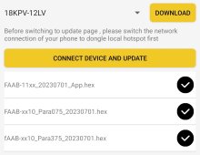
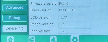
2nd edit - Attached a visual aid of the 3 files of the currently installed version of my system.
Screenshot_20230710_223245_EG4 Monitor.jpg
 

Attachments

  • 20230710_220024.jpg
    20230710_220024.jpg
    242.7 KB · Views: 8
Last edited:
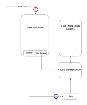
My 18kpv arrives tomorrow and based on the ongoing conversation I'd like to ensure I fully understand the proper CT placement. My current goal seems to be that of the majority of other users here. I intend to NEVER feed power back to the grid, however I will have the grid connected to the input of my 18kpv as shown in the diagram below. My question is whether I should be placing my CTs inside my main panel, or inside the inverter where it is being fed from the main panel?

I can potentially see this both ways, scenario 1: keeping them at the main panel allows for the 18kpv to 'backed' my main panel if my critical loads panel isn't pulling as much power as I'm creating. IE it's noon, my batteries are full, sun is out and I have 4kw of solar doing nothing, but I turn my electric dryer on which is connected to the main panel. Seemingly the inverter could sense this and allocate the 4kw to head upstream to the main panel (at least this is my understanding). Consequence there would be the dryer shutting off and boom, you've got a pretty fair amount of power likely to backfeed.

Scenario 2 (what I assume is safest): CTs inside the inverter, all settings set to never backfeed grid. If a situation arrises that the inverter doesn't function as we all are hoping, I would hope that the power being "accidentally" backfed to the main panel would have a decent chance of being "absorbed" by the loads in my main panel prior to exiting through the service entrance wires. I'm planning to strategically place the 50a breaker at the bottom of the panel, thus in theory it must move through the entire bus bar without finding a home before leaving, if that makes sense.

Can someone confirm what would be considered the "correct" way to install my CTs? Red circle being CTs at main entrance, blue circle being CTs at inverter

18kpv drawing.jpg
 
My 18kpv arrives tomorrow and based on the ongoing conversation I'd like to ensure I fully understand the proper CT placement. My current goal seems to be that of the majority of other users here. I intend to NEVER feed power back to the grid, however I will have the grid connected to the input of my 18kpv as shown in the diagram below. My question is whether I should be placing my CTs inside my main panel, or inside the inverter where it is being fed from the main panel?

I can potentially see this both ways, scenario 1: keeping them at the main panel allows for the 18kpv to 'backed' my main panel if my critical loads panel isn't pulling as much power as I'm creating. IE it's noon, my batteries are full, sun is out and I have 4kw of solar doing nothing, but I turn my electric dryer on which is connected to the main panel. Seemingly the inverter could sense this and allocate the 4kw to head upstream to the main panel (at least this is my understanding). Consequence there would be the dryer shutting off and boom, you've got a pretty fair amount of power likely to backfeed.

Scenario 2 (what I assume is safest): CTs inside the inverter, all settings set to never backfeed grid. If a situation arrises that the inverter doesn't function as we all are hoping, I would hope that the power being "accidentally" backfed to the main panel would have a decent chance of being "absorbed" by the loads in my main panel prior to exiting through the service entrance wires. I'm planning to strategically place the 50a breaker at the bottom of the panel, thus in theory it must move through the entire bus bar without finding a home before leaving, if that makes sense.

Can someone confirm what would be considered the "correct" way to install my CTs? Red circle being CTs at main entrance, blue circle being CTs at inverter

View attachment 156888
Ill cover this one step at a time.

CT red circle arrow facing down towards the inverter. One question...transfer switch defaults to the main panel...in the event of a loss of grid...the transfer switch flips to the 18kpv. Correct? I see it's a manual transfer switch, would be logical to have it default to the inverter.
 
Last edited:
Ill cover this one step at a time.

CT red circle arrow facing down towards the inverter. One question...transfer switch defaults to the main panel...in the event of a loss of grid...the transfer switch flips to the 18kpv. Correct?
Manual transfer switch, will always be set to 18kpv. The only time I would expect to switch it to grid power would be system maintenance or something failing.

With the transfer switch set to the 18kpv, I'm effectively still able to use grid power as it should draw from the main panel whatever it needs to supplement solar etc.
 
, scenario 1: keeping them at the main panel allows for the 18kpv to 'backed' my main panel if my critical loads panel isn't pulling as much power as I'm creating. IE it's noon, my batteries are full, sun is out and I have 4kw of solar doing nothing, but I turn my electric dryer on which is connected to the main panel. Seemingly the inverter could sense this and allocate the 4kw to head upstream to the main panel (at least this is my understanding). Consequence there would be the dryer shutting off and boom, you've got a pretty fair amount of power likely to backfeed.

Scenario 2 (what I assume is safest): CTs inside the inverter, all settings set to never backfeed grid. If a situation arrises that the inverter doesn't function as we all are hoping, I would hope that the power being "accidentally" backfed to the main panel would have a decent chance of being "absorbed" by the loads in my main panel prior to exiting through the service entrance wires. I'm planning to strategically place the 50a breaker at the bottom of the panel, thus in theory it must move through the entire bus bar without finding a home before leaving, if that makes sense.
I'd go with Scenario 1 - CT main panel and transfer switch set to pull from main by default the inverter by default.

Scenario 2 CT in the inverter would only support the critical load panel and transfer switch would default to the inverter, if the inverter went down the transfer switch would flip to the grid.
 
Last edited:
I'd go with Scenario 1 - CT main panel and transfer switch set to pull from main by default.

Scenario 2 CT with in the inverter would only support the critical load panel and transfer switch would default to the inverter, if the inverter went down the transfer switch would flip to the grid.
Sorry, I should have clarified, the transfer switch is manual, it will be set to inverter regardless.
 
Manual transfer switch, will always be set to 18kpv. The only time I would expect to switch it to grid power would be system maintenance or something failing.

With the transfer switch set to the 18kpv, I'm effectively still able to use grid power as it should draw from the main panel whatever it needs to supplement solar etc.
If you did it that way...Sounds like a power loop. Unless I'm missing something
 
As a side question, is it coming via UPS? I've never seen UPS driver having to deal with a 130lb+ box.
No, it's coming via R&L Carriers - Suggestion for the folks at Signature Solar - Update the website to provide accurate carrier tracking information. Mine has said "Fedex Calculated Shipping", had to call to get an idea of when it would be coming.
 
If you did it that way...Sounds like a power loop. Unless I'm missing something
Hopefully I'm not an idiot here lol..

Transfer switch enables one of the two scenarios, but not both at the same time:

Grid>transfer switch>subpanel

Grid>18kpv>transfer switch>subpanel

I'm not seeing the loop?
 
Hopefully I'm not an idiot here lol..

Transfer switch enables one of the two scenarios, but not both at the same time:

Grid>transfer switch>subpanel

Grid>18kpv>transfer switch>subpanel

I'm not seeing the loop?
I'll read it again later. Maybe I'm imagining....
 
Looking it over again...I'm not sure where I got the loop idea from.

RED if you want to feed/assist the main panel.

BLUE if you only want to power the critical load panel and not feed any power to the main panel. (The Blue CT location would allow the inverter to monitor Grid feed to the batteries and critical load.)
I would certainly like the ability to feed/assist the main panel, but NOT if it will create undue risk of back feeding the grid.

Generally speaking I think we'll use all the power created through the subpanel, but if not, I sure wouldn't mind assisting the main panel.
 
As a side question, is it coming via UPS? I've never seen UPS driver having to deal with a 130lb+ box.
Mine came UPS, I was his last stop for the day. I was around we unloaded it onto my pallet which was attached to my skid loader. It came much quicker than LTL. I had no say in this, SS set it up this way. Mine was not attached to any skid.
 
I would certainly like the ability to feed/assist the main panel, but NOT if it will create undue risk of back feeding the grid.

Generally speaking I think we'll use all the power created through the subpanel, but if not, I sure wouldn't mind assisting the main panel.
I was wrong.

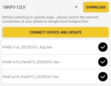
As of today. With the current firmware below...no grid backfeed. (Give it a few days and I'll pull the data from the electric company smart power meter and see what it says.)
Screenshot_20230710_223245_EG4 Monitor.jpg
 
Last edited:
As of today. With the current firmware below...no grid backfeed.
View attachment 156902
Good deal. I've got the power company coming out Thursday to do a 200a service upgrade, I'll be replacing my main panel and getting set up for the 18kpv install next week. I'll run a cat6 out to the main panel to get the CTs connected there (roughly 40 feet from the inverter).
 
Good deal. I've got the power company coming out Thursday to do a 200a service upgrade, I'll be replacing my main panel and getting set up for the 18kpv install next week. I'll run a cat6 out to the main panel to get the CTs connected there (roughly 40 feet from the inverter).
That sounds like my plan. CT main panel with a cat6 cable extension running to the inverter in my detached garage.
 
Ambient Temperature Questions:

So living in the frigid climate of Phoenix AZ, I've got my units mounted in a utility room off the garage, on the other side of the outside wall with the meter and the main panel, (which I'm only using now to feed a transfer switch). Since my original plan used different inverters, I cut a hole for a small 1/2T portable A/C, which was struggling because of the brownouts from the 4T on the roof. I insulated between the stud runs behind the inverters/cement board, and have insulation sitting here to do the better part of the room. So it's been around 110F (and higher) the last few days, and I've noted the fans don't even cut on on the units until the load gets north of 8KW. Ambient in the room hit around 114, and the temp gun shows the inverter cabinets ~147F. Should I just put in some ventilation and skip the A/C? This is the one aspect of these big beasts I find truly stunning. Not needing to run an A/C to protect the inverters is just huge, and thus far seems to be the case.
12kw Inverter Fan start and stop logic.
START : Total power higher than 6kW or max.
START : Inner temperature higher than 75 degrees Celsius
STOP: Total power lower than 4.8kW and max.
STOP: Inner temperature lower than 65 degrees Celsius.
 
There are new and improved firmware updates coming very soon, this may fix your problem.
I am running an interim firmware that drastically improved the load voltage regulation and power.
i have fAAB-1111 and LCD V11 dm if you want to update.
this improve zero export and ac couple..
 

diy solar

diy solar
Back
Top