diy solar

diy solar

EG4 18kPV Q+A general thread

Brownouts when at the edge of solar output. . .

Here is the problem. My panels are kicking 11100 watts at my 11000 watt load (Dryer && A/C). No problem. Panel output drops to 10900 watts, now I need 100W from the batteries. . . Brown-out, batteries kick in then everything is fine. It is unfortunate that I just happen to have a series of loads that lie squarely in this range. I'm wondering if there is a software fix for this, it's annoying. It wouldn't really do it if I had 4 more panels. Any thoughts or settings that might work around this? It would be more optimal if the batteries were to kick in at (say) 200W before they are actually needed, even better make it a setting.
battery will kicking based on the load of the inverter
 
Brownouts when at the edge of solar output. . .

Here is the problem. My panels are kicking 11100 watts at my 11000 watt load (Dryer && A/C). No problem. Panel output drops to 10900 watts, now I need 100W from the batteries. . . Brown-out, batteries kick in then everything is fine. It is unfortunate that I just happen to have a series of loads that lie squarely in this range. I'm wondering if there is a software fix for this, it's annoying. It wouldn't really do it if I had 4 more panels. Any thoughts or settings that might work around this? It would be more optimal if the batteries were to kick in at (say) 200W before they are actually needed, even better make it a setting.
I don't have that issue. Can you describe your brown out?
 
View attachment 156463
I'm literally right on the edge. Keeping in mind I have TWO(2) inverters both pretty much have identical input/output numbers. Also, this screen is "pretty" but kind of non-functional. It would be nice to have a 3 line display, with columns. one line for each inverter, and a total line. Clicking between is annoying.
is it configure as parallel?
 
View attachment 156463
I'm literally right on the edge. Keeping in mind I have TWO(2) inverters both pretty much have identical input/output numbers. Also, this screen is "pretty" but kind of non-functional. It would be nice to have a 3 line display, with columns. one line for each inverter, and a total line. Clicking between is annoying.

It would be nice to have a 3 line display, with columns. one line for each inverter, and a total line.
Agree that the web interface and app are lacking.

For the "Home" page I'd like to see all inverters within reason (PV1,2,3 status on each), battery bank(s) status, etc.... High level stuff.
Then give me a page or two to "nerd out" on - each battery status down to the cell level (volts, amps, temps....) - off in the weeds data. Truly know what's going on.
Charts with configurable time frame monitoring every 30 seconds would work, prefer every 10 seconds-

It is pretty.
More charts and options are coming soon. It is all being worked on at the moment.
 
Well, I pulled the trigger and hooked up my 18KPV to the grid. (Running some test). It's currently setup like a critical load panel. I have the CTs hooked up (not sure if the CTs are required in this setup, since I'm not attempting to "upfeed" to the main panel)

Even in that case, the inverter prefers the CT’s hooked up just to monitor the bypass usage. That’s my understanding of it anyway.
 
Well, I pulled the trigger and hooked up my 18KPV to the grid. (Running some test). It's currently setup like a critical load panel. I have the CTs hooked up (not sure if the CTs are required in this setup, since I'm not attempting to "upfeed" to the main panel)
install inside the inverter to the grid input wires, this will help if you don't want to export power from the inverter..
 
What I learned: updated 23 July

- Force Discharge (update 22 July not necessarily for my setup...may be useful for TOU)
- AC Charging (time, SOC, current)
- Limiting Force Discharge Current is neat
- I'm 90% certain that Reverse CT is flipping the CTs 180 degrees and not a left to right swap.
- No issues with voltage sag when connected to grid. (Firmware updates made grid disconnected improvements)

- Learned how to read the Smart Meter outside and verify flow direction. (Small arrow pointing right and little squares that travel right to left...)
- Peak-Shaving, I need to learn more -may not need since I'm using Force Discharge.
- Turning on StandBy allows grid to bypass inverter.
- Wondering If I need AC Charging enabled? It seems to bypass Force Discharge settings when times overlap.
 
Last edited:
What I learned:
- Force Discharge (should have been the first step)
- AC Charging (time, SOC, current)
- Limiting Force Discharge Current is neat
- I'm 90% certain that Reverse CT is flipping the CTs 180 degrees and not a left to right swap.
- No issues with voltage sag when connected to grid.
the grid is acting like a big transformer..
- Learned how to read the Smart Meter outside and verify flow direction. (Small arrow pointing right and little squares that travel right to left...)
- Peak-Shaving, I need to learn more -may not need since I'm using Force Discharge.
- Turning on StandBy allows grid to bypass inverter.
also you can use Charge First (PV) time when you don't want to discharge your battery during the night or when there's not enough solar production.
- Wondering If I need AC Charging enabled? It seems to bypass Force Discharge settings when times overlap.
when using other feature beside self-consumption, any time setting must not overlap with others, except charge first(pv) and AC Charge (these two features can time setting overlap).
 
is it configure as parallel?
Of course... That brings up another annoyance. Why don't the settings syncronize between the invertters? Some do, like if you kick standby it turns everything off. But like threshold settings for battery discharge do not. Also the book states that you should be in standby mode to make changes in parallel mode. This is totally unacceptable... Now you have to be in standby to take it in or out of parallel, that would make sense.
 
Of course... That brings up another annoyance. Why don't the settings syncronize between the invertters? Some do, like if you kick standby it turns everything off. But like threshold settings for battery discharge do not. Also the book states that you should be in standby mode to make changes in parallel mode. This is totally unacceptable... Now you have to be in standby to take it in or out of parallel, that would make sense.
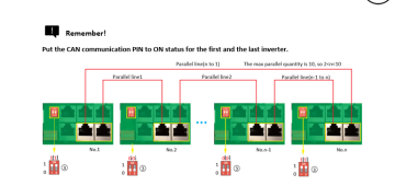
it must set correctly on the setting, to synchronize both inverter.dm with your inverter SN ot Dongle Sn and i will look into your setting. with that being said the parallel communication cable and dip switch is set and installed correctly
 
I don't have that issue. Can you describe your brown out?
It happens whenver it crosses the I need/don't need battery threshold. Again I have TWO inverters in parallel. The lighs in the house all DIM then recover. By DIM I mean almost but not quite turn off. I've got a sensor samplng every 5 seconds, I could make it a bit more agressive. This happened about every ten minutes or so until the dryer was done. Glacing at the sensor data:

myhouse=> select pwm_volts,pwm_stamp,pwm_sensor,pwm_amps,pwm_frequency from power_monitor where pwm_stamp > '2023-07-08 12:00:00' and pwm_volts < 113 order by pwm_volts
;
pwm_volts | pwm_stamp | pwm_sensor | pwm_amps | pwm_frequency
-----------+------------------------+------------+----------+---------------
99.6 | 2023-07-08 15:24:10-07 | 10 | 52.5830 | 59.8
100.8 | 2023-07-08 14:47:00-07 | 11 | 50.8970 | 59.9
101.7 | 2023-07-08 14:47:00-07 | 10 | 56.7960 | 59.8
103.0 | 2023-07-08 15:24:10-07 | 11 | 50.5000 | 59.8
104.4 | 2023-07-08 15:28:20-07 | 11 | 60.1410 | 59.9
105.5 | 2023-07-08 14:44:35-07 | 11 | 31.2630 | 59.9
106.1 | 2023-07-08 13:48:35-07 | 10 | 26.9300 | 59.9
106.8 | 2023-07-08 13:26:50-07 | 11 | 27.7590 | 59.9
106.9 | 2023-07-08 12:51:00-07 | 10 | 29.2530 | 59.9
106.9 | 2023-07-08 14:31:50-07 | 11 | 28.3340 | 59.9
107.0 | 2023-07-08 14:51:10-07 | 10 | 50.7780 | 59.8
108.6 | 2023-07-08 13:53:30-07 | 11 | 33.5700 | 59.9
109.1 | 2023-07-08 13:33:30-07 | 11 | 34.2150 | 59.9
110.1 | 2023-07-08 14:51:10-07 | 11 | 49.5430 | 59.8
110.7 | 2023-07-08 14:44:35-07 | 10 | 40.9720 | 59.9
110.8 | 2023-07-08 13:00:25-07 | 10 | 34.2240 | 59.8
111.6 | 2023-07-08 13:26:50-07 | 10 | 36.6680 | 59.9
111.6 | 2023-07-08 13:48:35-07 | 11 | 25.2380 | 59.9
112.1 | 2023-07-08 12:51:00-07 | 11 | 27.0720 | 59.9
112.1 | 2023-07-08 14:31:50-07 | 10 | 37.5540 | 59.9
112.4 | 2023-07-08 14:15:05-07 | 10 | 27.1060 | 59.9
112.6 | 2023-07-08 12:59:55-07 | 10 | 6.4160 | 60.0
112.7 | 2023-07-08 13:58:30-07 | 10 | 26.4820 | 59.9
112.8 | 2023-07-08 13:30:15-07 | 10 | 27.2910 | 59.9
(24 rows)


If you go a little deeper

myhouse=> select count(*) from power_monitor where pwm_stamp > '2023-07-08 12:00:00' and pwm_volts < 115;
;
count
-------
40
(1 row)

myhouse=> select count(*) from power_monitor where pwm_stamp > '2023-07-08 12:00:00'
myhouse-> ;
count
-------
13474
(1 row)
 
Just give it a few days, these two issues are currently being addressed and there will be a firmware update very soon.
 
it must set correctly on the setting, to synchronize both inverter.dm with your inverter SN ot Dongle Sn and i will look into your setting. with that being said the parallel communication cable and dip switch is set and installed correctly
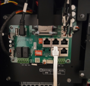
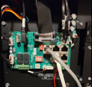
I'm sure there is a language gap, and I asked specifically about this to support. I have a single cable connected, and I believe the DIP switches are up on the primary. The manual had a continuous loop, daisy chain with the switches up on two devices. MMMV.

Secondary:
1688866117646.png


Primary:
1688866639865.png
 
@GRV0423 ... And while you are at it I'd love some insight on getting a modbus call to work. I've a computer (Now an Orange Pi 5) with an 8 port RS-485 relay and 3 AC/AMP sensors monitoring my load. Based on time/current thresholds Im toggling some relays to turn off/on the EV charger. I'd like to add some of the numbers from the inverter to the mix:

[keith@powercontrol] /home/keith<302>panelmonitor --show

Panel Monitor Status

RS-485 device: /dev/ttyUSB0
Log Level: 3
Reset Energy: monthly on day 1
Polling Interval: 5
Sensors: 10 11 12
Relays:
Minimum Off Time: 600
Id Label Activate State
---- ---------------------- --------- -----
1 Pedestal (5/1) NORMAL OFF
2 E/V Charger (5/2) NORMAL OFF
3 Oven / Range (5/3) REVERSE OFF
4 Grid Power (5/4) NORMAL OFF
Triggers:
Amps/Draw Schedule
Id On Off Day Time State Comment
1 50 75 Any 12:30:00 ON Pedestal only under sunlight
1 50 75 Any 16:00:00 OFF Pedestal only under sunlight
2 55 85 Any 12:30:00 ON EV/Garage only under sunlight
2 55 85 Any 17:00:00 OFF EV/Garage only under sunlight
3 90 70 Any ON Range Only by load
4 200 200 Sun 07:00:00 OFF Sun Morning
4 200 200 Sun 23:55:00 ON Sun Evening
4 200 200 Mon 07:00:00 OFF Off Mon 1300
4 200 200 Mon 23:55:00 ON On Mon 2000
4 200 200 Tue 07:00:00 OFF Off Tue 1300
4 200 200 Tue 23:55:00 ON On Tue 2000
4 200 200 Wed 07:00:00 OFF Off Wed 1300
4 200 200 Wed 23:55:00 ON On Wed 2000
4 200 200 Thu 07:00:00 OFF Off Thu 1300
4 200 200 Thu 23:55:00 ON On Thu 2000
4 200 200 Fri 07:00:00 OFF Off Fri 1300
4 200 200 Fri 23:55:00 ON On Fri 2000
4 200 200 Sat 07:00:00 OFF Sat Morning
4 200 200 Sat 23:55:00 ON Sat Evening
 
Back
Top