that is an old wives tail and not true from a strickly technical standpoint.
Setting a car battery on concrete that is cold like most of the US and Canada makes the battery cold. When a battery cold it slows down the chemical reaction inside it that makes it a battery. But, it doesn't magically bleed electrons through the case. It is no different than just being cold in the car.
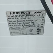
Term deffinitions -
Isc = current short circuit ('I' is the symbol for current) - This is with the wires touching nothing but meter leads
Voc = Voltage open circuit - this is with the wires touching nothing but meter leads
vmp = Maximum operating voltage = this is the max voltage in full sun while connected to a PWM
Imp = maximum power current = this is the max amps in full sun while connected to the PWM
pm = Maximum powere = vmp * imp = watts out - so this is the maximum power a panel can push.
Your meter basics ---
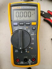
The hookups are like mine - you should always have the black wire in the center hole - it is common.
The right hole is for volts and ohms and smaller amp readings. This is the normal position for the red wire.
The left hole is where the red wire would go for reading up to 10 amps.
View attachment 208182
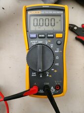
Put your black lead in the middle and your red lead in the left and set to DC current and then connect the wires.
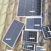
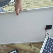
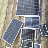
For the reading we need from your panels - wrap the wire from the solar panels around leads to get a firm connection - there are aligator clips that go over the tips of the probes to grab wires with that would be better if you have them.
View attachment 208190
From your video I grabbed this screen shot while you were reading it out. -- You have a 20amp PWM charge controller with 50v --- this should do nicely to start with. Instead of taking videos of things - just take clear still images - shorter and simpler to see.
View attachment 208183
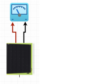
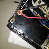
If you leave your panel hooked straight to your UPS battery you will make that battery kaput - so make sure to hook things up like this - make sure the red wires are in the + screw on the PWM and the black are in the - screw of the PWM. Make sure the right two screws are not used they are for a load that is no more than a 12vdc light bulb. Just don't use them.
Read the manual that should have come with it and make sure the battery type is set to SLA (sealed lead acid) or just Lead acid. If it allows you to set max charge amps set to 3 amps or less.
If you hook up the output from the PWM to the battery while the battery is also connected to the UPS there is a VERY HIGH chance you will make the UPS kaput. This is becuse the UPS charger is trying to vary the voltage by manipulating the voltage regulator to maintain a constant charge current and it depends on the battery resistance going up to know when it is full.
If you introduce the separate current coming in from the PWM that can confuse things and heat the UPS circuit way past its limits.... and kaput.
Now - that battery in the UPS can take a maximum current of about 1.8 to 2 amps. If you connect more amps through there than that you will fry it in a few hours.
View attachment 208186


")