diy solar

diy solar

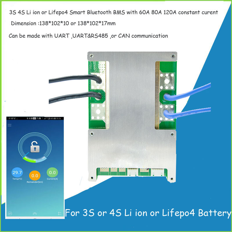
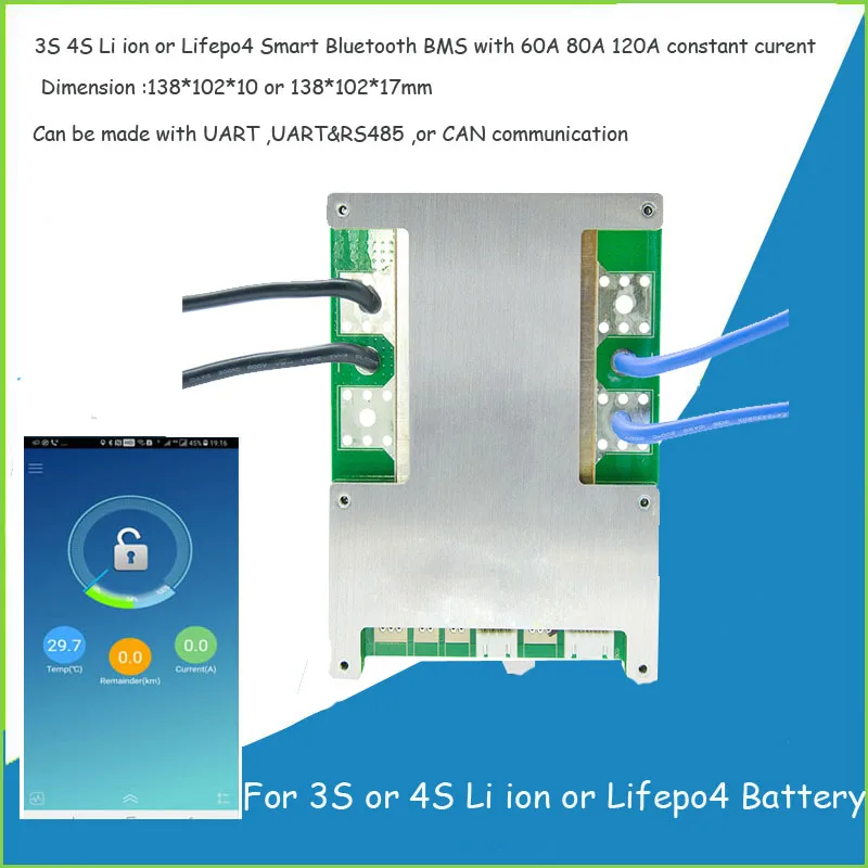
Finally found a LiFePO4 BMS with Low-temp Charging Protection

I learned the hard way when tinkering with IoT that it has to be connected to the internet to work and n the case of Samsung's SmartThings, they want full access to everything on your phone (address book, gps, photo's, mail, web browser etc_)

Yup. I have a lot of home automation stuff, but I make sure everything I can make so is purely local. Which means 90% of my IoT devices are on wifi, re-flashed with 3rd party FOSS firmware, and they only talk to my locally-running hub software.
 
Yup. I have a lot of home automation stuff, but I make sure everything I can make so is purely local. Which means 90% of my IoT devices are on wifi, re-flashed with 3rd party FOSS firmware, and they only talk to my locally-running hub software.
I briefly looked a HASS.IO but, as I only want to have internet up when I want (Off gridder and satellite modem is a pig) so I'm in a lurch there for now.
 
Hey, newbie to the forum, found my way here from the video about this BMS since it seems to fit exactly the need I have: 100Ah capacity, 100A draw.

One question though: for my application, a hard-wired display of battery data (especially state of charge and charge/discharge rate) is more useful than Bluetooth to a phone. Is there any option for that with this bms? Or another model that has the same features (4S, 100A, and low-temp protection)? Or would I need to use a separate device with a hall sensor or shunt to get that?

ETA: oh, and just noticed the app is android only. That's pretty much a deal killer for me - I have an iPhone.... So alternative ways to program this BMS? Or another with similair features?

On Wills video he lists a link for install on iOS phones.???

 
It seems the BMS' that have Bluetooth apps are all android based, haven't seen others with alternate phone apps.

I have an IPhone App for the one that came with my battery .... and it has low temp cutoff.

I tried loading software to my PC called BlueStacks that will run Android apps on the PC and loaded the file Will posted for the BMS he is recommending. The software runs the App but won't connect to my battery ..... not sure if its my setup or if it is a different app.

Edit .... Just saw that Will has linked an IPhone app .... gonna check it out and see if it is what I am using.

Edit2 ... That is the same App I'm using for my BMS ..... Not sure why the android app doesn't connect from my PC.
 
Thanks all, missed the ios app. I'd still prefer something that uses a physical display rather than blue tooth.
 
I'd still prefer something that uses a physical display rather than blue tooth.

I hear you! Particularly the SOC (state of charge). Having to get a phone out to check on your SOC is a pain.... I would much prefer glancing at the display. If I need to see the other stuff (Voltages, Currents, temps, cycle counts, etc, etc then I am doing something more detailed and getting the phone out is less of an issue)

The board has a communications port. If someone had the protocol details they could probably code a small hobby display to do the job.... but I am not going to try doing that. It is to much work compared to buying the cheap $40 Ali battery monitor.
I'm thinking about getting the Chargery 8T controller instead. Am I missing some major advantage to this BMS compared to their unit, other than price?
 
I'm thinking about getting the Chargery 8T controller instead. Am I missing some major advantage to this BMS compared to their unit, other than price?
Chargery looks like a nice BMS, but I have no first hand experience with it.

My biggest issue with the chargery is that it requires external control for shutting off charge and/or discharge. The default would be to use big relays to cut charge and discharge power (Two of them). Some people have apparently been able to use the relay outputs as signals to other equipment to do the same, but that only works if your other equipment can take the signals. The relays they recommend are supposedly fairly low wattage so it may not be too bad for larger systems, but if you are tight on available amp-hours, this may not be the right thing for you.

If you are ok with the relays, a really nice accessory is their delay module that can be used to set up an automagic precharge circuit for when connecting to the inverter.

I actually rather like the relay thing, as I'm a big fan of there being a physical disconnect somewhere in the system. With 100Ah, I don't think the relay draw would be real significant. If I were to use something with no relay, I'd probably put one in, anyway, with a "master" type switch anyway... Yes, the delay board definitely looks quite nice.

I'd love to use latching relays for this, but they aren't supported by the BMS and all the ones I've ever seen are stupid expensive anyway....

ETA: I can even wire the relay control circuit such that there was a mechanical "Master" switch that prevented the BMS from turning the system back on.
 
I'd love to use latching relays for this, but they aren't supported by the BMS and all the ones I've ever seen are stupid expensive anyway....

I've just ordered this driver circuit and this latching relay to use with the Chargery BMS (at least on the discharge end, charge signal will be directly hooked-up to the inverter-charger). If background consumption is an issue for you that's a nice potential solution, the latching relays don't draw anything and the driver circuit will take care of toggling it according to the signal sent by the BMS. The driver circuit itself goes to sleep when not triggered and consumes virtually nothing (35uA according to the datasheet)
 
@jgalak. It sounds like you are good to go. Like I said, I don't have direct experience with it but others on the forum seem to like them.

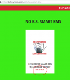
The fact that the Battery Hookup BMS is out of stock kinda pushes you to the Chargery too.

BTW: In another thread a poster said he was getting a Chargery firmware upgrade to enable low-temp disconnect. If you need this, make sure your version of the BMS has it.
 
Last edited:
I've just ordered this driver circuit and this latching relay to use with the Chargery BMS (at least on the discharge end, charge signal will be directly hooked-up to the inverter-charger). If background consumption is an issue for you that's a nice potential solution, the latching relays don't draw anything and the driver circuit will take care of toggling it according to the signal sent by the BMS. The driver circuit itself goes to sleep when not triggered and consumes virtually nothing (35uA according to the datasheet)

That's a nice solution! The relay is a little lower current than I would like, but there are others available.
 
Speaking of current draw..... does anyone know the current draw of the battery hookup BMS when everything is stopped (Not charging or discharging). (I am wondering about discharge while storing the battery.)

Along those lines, is there a good way to turn off the BMS while in storage so there is no current draw? I could always disconnect it, but it would be nice if I could flip a switch or press a button to completely shut it off.
 
Just order direct! You can even get a 120amp version. They come with 3x 10 gauge wire;)


Or


Just order direct! You can even get a 120amp version. They come with 3x 10 gauge wire;)


Or


Has the manufacturer incorporated the low-temp cut-off firmware upgrade. My understanding is that Battery-hookup is having a 3rd party custom flash new firmware
 
Last edited:
I've just ordered this driver circuit and this latching relay to use with the Chargery BMS (at least on the discharge end, charge signal will be directly hooked-up to the inverter-charger). If background consumption is an issue for you that's a nice potential solution, the latching relays don't draw anything and the driver circuit will take care of toggling it according to the signal sent by the BMS. The driver circuit itself goes to sleep when not triggered and consumes virtually nothing (35uA according to the datasheet)


Ooh, that's a really clever idea. Just need to find a US source. Might be able to design the driving circuit myself....
 
I just sent the Mfg a question if they can incorporate the low temp cutoff. Also, I would like to have this BMS in 8S 24V 100A.
 
When I talked to battery hookup last Thursday they said they expect to get an 8S version of these in in 2-3 weeks. The price should be less than $20 more.
 
When I talked to battery hookup last Thursday they said they expect to get an 8S version of these in in 2-3 weeks. The price should be less than $20 more.
The 8S version I saw on the Mfg website was only 60A ..... Probably what battery hookup is getting too. I need to get my BMS ordered soon since I already ordered my cells. May have to go with the Chargery.
 
The one I ordered does, all I had to do was to use the app and set my temperature value. The glass has ice and water and Low temp cut of is set to 8.0deg C (sorry for the bad photo)


Using the app the BMS is being reported as:
Device Model : JBD-SP04S20-L4S-120A-B-U
Production Date : 2019-12-3
manufacturer : DGJBD


Has the manufacturer incorporated the low-temp cut-off firmware upgrade. My understanding is that Battery-hookup is having a 3rd party custom flash new firmware
 

Attachments

  • fullsizeoutput_3a0.jpeg
    fullsizeoutput_3a0.jpeg
    70.4 KB · Views: 62
Last edited:
Does anyone know what exactly is Battery Hookups Nickel Fuse Shipping,
It was their cheapest shipping option.
I find nothing anywhere pertaining to what
Nickel Fuse US shipping is. ✌

I just got my BMS.... it came FedEx. I think Nickel Fuse US shipping is their 'code' for whatever they decide to use.
 
I just got my BMS.... it came FedEx. I think Nickel Fuse US shipping is their 'code' for whatever they decide to use.

They apparently have three levels of customer shipping cost, $$$, $$, $. Nickel Fuse is their name for slowest econo shipping it seems, probably ground 5-7 business days. Next level up is 3 day (fedex) and the top level is likely next day. You get those choices at check out.
I ordered last Saturday. Hopefully it will come Friday. ?
 
Spent the last few days and tonight testing BMS:

1. The "new" daly LiFePO4 BMS (that states in the data sheet that it has low temp charging protection) does not have low temp charging protection. And yes, it has a temp sensor attached. This disappointed me big time. Video to come.

2. Next, I programmed/tested this BMS for a couple of days:
View attachment 4222

And it failed. App would crash. Default low temp cut off was -5 degrees C. No manual and very difficult to work with. Had a lot of issues with it. Will cover every downside in my upcoming video. Avoid this BMS.


3. Then I tested the battery hook up 100A BMS that arrived this afternoon:
View attachment 4223
And low temp cut off was programmable and worked perfectly. Bluetooth connected perfectly as well. I was excited so I did a load test of 200Wh with 90-102A continious. Passed with flying colors, then pushed it passed its limit and it disconnected the loads. Heatsink stayed warm and did not heat up excessively.

I'll make a long video covering all these things and the testing methods, but I am going to go with this bms from now on. I am so tired of other bms failing. The battery hookup one is used on medical devices as well, which I need more information on.

The number one most important thing to know when using this bms is that you need the proper app. The app on the website is NOT what you want. You need the "enterprise" version:
Click Here for APK of enterprise BMS program app

Send it to your phone with an email (not gmail), then install in on your phone, then connect to bms.

Then go to parameter settings and change the low temp charging cut off to 2 degrees Celsius. Then the reconnect voltage to 5 degrees Celsius.

You can buy this bms by clicking here (my affiliate link) and the coupon code is "SOLAR" for 10% off. I am going to get a 8s model and build a big system with it. I like this bms a lot, so will be testing it like crazy. I also will make a DIY video on how to use it in the next couple days (possibly tomorrow if I get enough sleep tonight).

Biggest downside of this bms is 2x 10 gauge wires at P- and B-. But it has a hole and solder tabs for adding more wires.

Just wanted you guys to know about all this before you waste your money on the first 2 bms. I wasted $150 on those bms and they were a total rip off. The new bms seems to kick butt, so videos to come. :)
I did notice that in the APP it say the attached battery is a 100ah when in fact it is a 200ah. I do not know if this a setup issue or not.
 

diy solar

diy solar
Back
Top