diy solar

diy solar

Finally found a LiFePO4 BMS with Low-temp Charging Protection

Hey, new question... where is the best place to position the temp sensor? I am building a 4S battery using CALM 130 Ah cells. I could tape the sensor to the side like Will did. OR I could feed the sensor down between the two center cells. My thought was that I'd get a better idea of the temp of the mass of the cells vs. the temp of the skin.

But, not sure if that is really a good idea or not. If the skin is close to freezing temp, then THAT is the time to shut off charging, rather than waiting for the center of the battery to get that cold.

Gee... maybe I answered my own question. Thoughts?
 
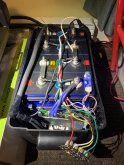
I taped mine on the QR code on the top, it's directly on the aluminium case and will have less chance of getting damaged.IMG_0989.jpeg
 
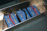
I just test fit my 3 batteries in the custom box I've built... they don't fit as expected after I added the all-thread to pull them together. My design evolves once again.
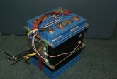
Pretty sure I'll just tape the temp sensor to the outside of the battery. The pic below shows the temp sensor placed between cells, but I'll move it to the outside of the battery.
Originally, the 3 batteries were going to fit lengthwise with the inverter and all the other bits crammed into that box. but now, looks like the inverter will live inside the camper and only circuit protection gear will be in the box. The box is designed to fit in the A-frame at the front of my camper, where the original FLA batteries sat.

sm_DSC06786.jpgsm_DSC06785.jpg
 
Oh, wanted to ask, when I parallel these batteries is it best to keep the cables all the same length between the batteries and the bus bar? I've read a few threads about keeping those cables the same length for the purpose of evenly distributing the load and charge between the batteries. That had never occurred to me before...
 
There is a lot of opinions around this.

No matter what, the most important thing is to make sure you have properly gauged wires with excellent crimps/connections. If you don't do this, the length is the least of your problems


Are you going to wire the 3 12 volt banks in series? If so, the most important thing is to keep everything as short as reasonably possible.

Are you going to wire the 3 12 volt banks in parallel? If so, there are a lot of opinions but not a lot of science to back them up. (This is true of some sources that are otherwise very credible and knowledgeable.)

I have seen a few different claims on the 'only way that works', they boil down to 3 claims

Parallel Option 1: It does not matter, just hook 'em up

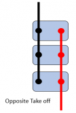
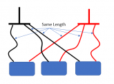
Parallel Option 2: Tap the negative and positive from opposite batteries (In these pictures, each blue rectangle is one of your 12V banks)
1581182122702.png
Parallel option 3: Equal length wires to common bus bars
1581181919676.png

Which should you do? I go with option 2.

There is also a belief that you must keep the length of the cables going from the batteries to the rest of the system the same length. I do not believe this at all. In fact, I believe it is counter productive. If you make a cable slightly longer to 'match' the other, all you are doing is adding resistance to the round trip path.
 
Option 1 is crappy.
Option 2 is far better but not perfect if more than 2 batteries.
Option 3 is perfect but often hard to do in practice, so we choose option 2 most of the time.

There is also a belief that you must keep the length of the cables going from the batteries to the rest of the system the same length. I do not believe this at all. In fact, I believe it is counter productive. If you make a cable slightly longer to 'match' the other, all you are doing is adding resistance to the round trip path.

Yeah that's pure BS in DC (but it matters for high frequency stuff), you just increase the losses for absolutely no reason. Shorter is always better.
 
Shortest Same Length cable of the "Right Gauge" is always best but not tight so there is no movement, you need to leave a bit of play for shifting things around, and working on your gear. IF using a BUS topology same length cable is highly suggested. Its how I have been taught & trained over the decades.

All opinions on the internet are opinions and must be treated as such. Do what sounds & looks most reasonable & logical (pennies & dollars are moot) which does not compromise safety, quality or generally "good practices" and that is where your critical thinking comes into play.

Some will tell you to keep your DC wire separate (you get RFI and EM issues) or keep them as close to each other as possible (to cut generated external effects) which is what I suggest always. Simple to test, use an AM radio (that is if you can find one). Such interference can affect Cell Phones, Wifi, Bluetooth and more.
 
1. Does this BMS directly support CANBUS?
2. Can this BMS support CANBUS via a software interface such as on a Linux server (e.g., a Raspberry Pi)?

I ask because I'm starting to find solar charge controller inverters like the SolArk that say they require it.


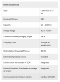
For instance, from that Sol-Ark 8K, here is the screenshot:
Screen Shot 2020-02-08 at 11.56.08.png

The very last line says "Communications to Lithium battery": "CanBus & RS485".

So, I believe that means it needs CANBus over an RS485 connection.
 
Waiting for my two 120a units to arrive. Does anyone know the rated surge/overcurrent capabilities of these?

(I.e 135 amps for 10 seconds, 150a for 3s, etc).
 
I have the 120A units, but no batteries (damn you alibaba).

I have a similar question as Turd. The different Amp rating of the models just seem to have more 10g wires soldered in. What is the actual constant current and overcurrent capability for what time?

I suspect we will get no answer from the manufacturer, but the thing is made up of large mosfets. Do these mosfets have a rating that can be known by the markings or dimensions of them?

Can 120A be passed through continuously the 120A version, can 200A be passed through for 1s? etc...

Thanks x 1,000,000.
 
Agreed. Please a pic of the circuit board or find the part number on the mosfets. We can check the data sheets.
 
1. Does this BMS directly support CANBUS?
2. Can this BMS support CANBUS via a software interface such as on a Linux server (e.g., a Raspberry Pi)?

I ask because I'm starting to find solar charge controller inverters like the SolArk that say they require it.


For instance, from that Sol-Ark 8K, here is the screenshot:
View attachment 6907

The very last line says "Communications to Lithium battery": "CanBus & RS485".

So, I believe that means it needs CANBus over an RS485 connection.

I think it does support CanBus. Look at this picture of the BMS from Battery Hook-up:
1581279139341.png

There are several unpopulated headers. I would love to get more details on their use. From left to right the connections are:

Connector 1
  • CANH
  • CANL
  • GND
Connector 2
  • B
  • A
Connector 3
  • SW
  • SW
Connector 4 (Populated)
  • Bluetooth Dongle
Header 5
  • BAt+
  • NC
  • BAT-
Header 6 (Populated)
  • Cell connections

If anyone has information on the unused headers I would love to hear about it.
 
SW/SW is probably for a switch, and A/B I don't know, you need to follow the tracks to see where they go and guess from that.
 
BTW: Those connectors are 2.5mm JST-XH. It would be easy to get headers that would solder into place.
 
SW/SW is probably for a switch, and A/B I don't know, you need to follow the tracks to see where they go and guess from that.
Yup.... that would be my guess as well. Here is my guess for each:

Connector 1 Guess: CanBus. Assuming the SW on the board supports it this could be interesting (but we would have to know more details to use it)
  • CANH
  • CANL
  • GND
Connector 2 Wild Guess: An output signal of some kind.
  • B
  • A
Connector 3: Guess: On/OFF Switch The interesting thing is that without the header this is open. Perhaps it is Closed=Off.
  • SW
  • SW
Connector 4 (Populated) Known Bluetooth Dongle

Header 5: Guess: Connections to battery. By the name it looks like connections to the Battery +/-. Perhaps this allows the BMS to be powered when the battery is otherwise disconnected.
  • BAt+
  • NC
  • BAT-
Header 6 (Populated): Known: Cell connections
 
you need to follow the tracks to see where they go and guess from that.
I can't see the traces due to the heat sinks and the heat sinks are thermally bonded to the FETs so I don't want to remove them unless I know more and are likely to use the extra headers.

I put an ohmmeter on the pins between the Big battery- wires and the blank header pins. I only found a direct connection between the BAT- header pin and the big B- wire.

I tried the ohmmeter between the positive most cell lead and the empty headers and found no direct connections. (I kinda thought the BAT+ and the positive most cell lead might be connected.)
 
I can't see the traces due to the heat sinks and the heat sinks are thermally bonded to the FETs so I don't want to remove them unless I know more and are likely to use the extra headers.

Ok I see.

Yep, con1 is definitely a CAN bus, no doubt about that. Then the question is "is it enabled in software?"

Bat+ is probably connected to a voltage regulator. It is most likely kept separate from the most positive cell because it's not a good idea to use a wire carrying current to do a voltage measurement if you want to be precise.

Also, there's a lot of unpopulated components near those headers so I wouldn't have too much hope about using them.
 
Also, there's a lot of unpopulated components near those headers so I wouldn't have too much hope about using them.

Yup.... there is a good chance this is a de-featured board. Most of the unpopulated components are near connector 1, 2 & 3 so it is a long shot that any of them work.
 
Back
Top