diy solar

diy solar

Grounding of Solar Panels and Rails

Just asking, …..I must be missing somthing….when bonding my panel's I took continuity readings and found that all 4 sides did not show any continuity with each other …be it small gap where they are cut at 45’s or oxidation ….or both ..if all 4 sides are not showing electrical contact how does just doing one piece of the frame bond all 4 pieces..
have never understood thst concept….
That's weird. I have never actually checked continuity. I just assumed that it existed. Maybe it's just the brand you have? My panel frames are bolted together at the corners.
 
That's exactly why I'm scared to do it if it involves climbing up the roof again ?.

But each separated section of thr array... You mean when the 4m long aluminium rail joins with another sectkon of 4m rail or so? Then I think I habe 4-5 of these per each string
Basically you need grounding continuity throughout the entire array. Weebs connect everything together. So that you only need to ground the rails.
 
Just asking, …..I must be missing somthing….when bonding my panel's I took continuity readings and found that all 4 sides did not show any continuity with each other …be it small gap where they are cut at 45’s or oxidation ….or both ..if all 4 sides are not showing electrical contact how does just doing one piece of the frame bond all 4 pieces..
have never understood thst concept….
Great question. I will measure the 4 different types of panels I have and report back soon.
 
Rail mounting systems and panel documentation usually tells you that the clamps pierce the anodizing thereby connecting the panels to the rails and then you only have to connect one rail per set of panels to ground.
Grounding helps to protect you from two different things.
1. If your panel develops a problem and the DC voltage gets onto the frame and
2. Bleeds static electricity and induced voltage from nearby lightning strikes to ground. If you get a direct strike all bets are absolutely off.
 
That's weird. I have never actually checked continuity. I just assumed that it existed. Maybe it's just the brand you have? My panel frames are bolted together at the corners.
Not sure how the frames are connected…. They are touching at some points but no bolts…they seem strong , work great and produce 90 to 100+ % of rating most everyday it’s sunny, but they had no electrical contact at all within the 4 anodized aluminum that form the frame… …

I have Heard of this online here and there …that’s why I checked them before installing…
I found a workaround and all frames are bonded very well.and tied to everything else metal and all read continuity and same on the volt meters and whatever …the next panels I buy I will check how they are tied together..intresting…..
thank for the input.
J.
 
Rail mounting systems and panel documentation usually tells you that the clamps pierce the anodizing thereby connecting the panels to the rails and then you only have to connect one rail per set of panels to ground.
Grounding helps to protect you from two different things.
1. If your panel develops a problem and the DC voltage gets onto the frame and
2. Bleeds static electricity and induced voltage from nearby lightning strikes to ground. If you get a direct strike all bets are absolutely off.
I have no metal rails… mine are mounted on 2x4s cut to fit 4 panels per string…then those sections are mounted on 2x6 frames…3 ft of ground, tilt , run cool , cheap and works great…
I have never had other multiple panels before these..I was just wondering if everyone had this issue…
 
A few manufacturers claim to just isolate the copper from the aluminum with a stainless-steel washers.
 
I have no metal rails… mine are mounted on 2x4s cut to fit 4 panels per string…then those sections are mounted on 2x6 frames…3 ft of ground, tilt , run cool , cheap and works great…
I have never had other multiple panels before these..I was just wondering if everyone had this issue…
Same on mine. Wood Rails DIY. All panels bonded/connected as earlier in this thread.
 
Same on mine. Wood Rails DIY. All panels bonded/connected as earlier in this thread.
Each panel , or each of the 4 sides on each panel.…? That tis the question…..one is easy and one is a pain in the ass……
 
Each panel , or each of the 4 sides on each panel.…? That tis the question…..one is easy and one is a pain in the ass……
I'm willing to bet that most panels are going to have a loss of continuity across the four sides of the frame, simply from the way they are constructed. That is, unless the manufacturer purposely bonded all four sides. I don't recall seeing anything about that in any documentation. Which makes me think there are millions of panels installed this way. I have a couple questions on that -
1. If this is a major issue why has it not been addressed before now?
2. What would be the result of a short circuit in this scenario?
Okay three questions ...
3. Why haven't we been bombarded with cases where there has been some type of negative outcome such equipment damage or someone being electrocuted or at least having the hell shocked out of them?

I'm not arguing that it's not a common thing at all, just wondering if it's a critical thing.
 
Each panel , or each of the 4 sides on each panel.…? That tis the question…..one is easy and one is a pain in the ass……
Mine are just dual long (11') runs of wood rails. Then lay (3) panels across them. Bolt them in place. Tight, wind resistant, inexpensive. DIY metal mounts lag bolted into roof rafter underneath metal roofing. DIY Metal mounts spaced 5" tall above roof for me to access wiring if needed.
 
I'm willing to bet that most panels are going to have a loss of continuity across the four sides of the frame, simply from the way they are constructed. That is, unless the manufacturer purposely bonded all four sides. I don't recall seeing anything about that in any documentation. Which makes me think there are millions of panels installed this way. I have a couple questions on that -
1. If this is a major issue why has it not been addressed before now?
2. What would be the result of a short circuit in this scenario?
Okay three questions ...
3. Why haven't we been bombarded with cases where there has been some type of negative outcome such equipment damage or someone being electrocuted or at least having the hell shocked out of them?

I'm not arguing that it's not a common thing at all, just wondering if it's a critical thing.
Beats me… i never said it was a issue ,much less a big one…I don’t know…that’s why I asked Tim..
I have read online of some places that require all four side to be bonded to get approval… it’s a big country…lotsa different inspectors…
I have seen it discussed in several places…Thats why when I got mine I noticed the gap between the side corners … so I test all of them…no continuity at all …Zero … nada…
I do not know any solid answers but my learning would suggest to me ,depending on the voltage being run , if that they were not all tied together to trip a breaker or clear a fault and some got shorted and some didn’t there could be a potential difference… is it 21 volts ..it’s it 90 volts or 300 ..?

I don’t know exactly what could the consequence could be..I’m sure one of these other cats will know…but it probably depends on several conditions ..
But I do know this … if your panels are not connected “somehow in some way “ to each other I do not see how that can be called a proper bond…ya got pieces of metal all over the place that could be touched at different potentials..
I say the rails and the weeb comectors probably help the situation…plus most folks don’t go crawling around their panels everyday on the roof…( I think)
my are mounted 3 ft off the ground on a steel trailer… on a wooded platform.all of them and the combiner box and tied together with good continuity and tied to a chassis bus bus bar on the trailer that is has a six gauge wire leading back to a single electrode tied to the multiplus and the rest of the gear…everything is all tied together at one point..
. I touch my panels everyday in different spots when tilting them..if I’m standing in wet grass and touching a grounded chassis to the tailor and an unbonded shorted frame at the same time, 90 volts could run through me ……it may get me..it may not… depends on conditions…

back in the old days we had 2 solar panels on the boat….. nobody ever bonded anything to anything ….we just hooked em up to help charge the batteries at 12 v…..a different world..

I still ask the same question, if you don’t have continuity, how can everything be bonded to the same potential…maybe I got a weird set of renogy panels… I don’t know…

Said in all seriousness… I simply don’t know…that’s why I asked….?
 
Mine are just dual long (11') runs of wood rails. Then lay (3) panels across them. Bolt them in place. Tight, wind resistant, inexpensive. DIY metal mounts lag bolted into roof rafter underneath metal roofing. DIY Metal mounts spaced 5" tall above roof for me to access wiring if needed.
So how did you bond them…with what… or did you…?
 
Not yet. Work in progress. Still working to shift older panels and mount larger units. Then all will be grounded/bonded, similar as earlier in this thread. No issues to date without it, but I will get them connected.
Haaaaa… the ole work in progress thing…. The story of my life…when I go it will probably take the Drs a month to figure out if I’m dead , or just dyeing , but can’t quite complete the task..
 
With some of these cheaper AIOs, where are people landing the ground coming from the PV array? For example an EG4 6500.
 
With some of these cheaper AIOs, where are people landing the ground coming from the PV array? For example an EG4 6500.
All grounding goes back to the existing grounding system. (Existing main panel ground bar, existing ground rod, or some other part of the existing grounding system)
 
All grounding goes back to the existing grounding system. (Existing main panel ground bar, existing ground rod, or some other part of the existing grounding system)
I assume you mean exclusively pure grounding or bonding.

For purposes of lightning protection you usually want a dedicated grounding/earthing rod in the ground at some distance from the others.

This is to have a "clean earth" (for all other purposes) and a "polluted earth" (when lightning strikes).

I am not sure if you need to connect the two together though, but if you do, I believe there are some minimum cable lengths to ensure that enough decoupling occurs at high frequency (10/350 us lightning wave for instance).
 
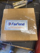
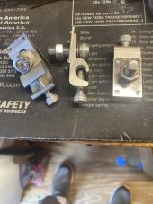
i have seen many folks here , including me , ask what’s a good grounding lug to bond panels that will avoid the copper/ alum issues ..I ordered a few types to look at them…FWIW ,I settled on these..they only connect the panels to each other electrically …don’t think they hold the panel to the rails as far as I can see. But they might in some cases… i do t know…..
I didn’t need nor want that feature anyway…
Look great, machined well, very secure when locked down , and a great finish.. Made of stainless and aluminum and somthing else..??? whatever… got em on Amazon..

The 4 little protrusions cut right thru any anodization or oxide coating on the frames when tightening down…
they were easy to install and fasten to the wire.,If you can get to your panels underside…..I did use one 90 ft long piece of 6 ga stranded copper ground wire and removed about an inch of insulation at each lug.
I coated the bare wire very well with a heavy coat of No-a-Lox to keep water from creeping into the wire at the bare spots.
also the lug, and the mating surface on the frame before tightening stuff down.
it all went great …..took a while ………all meter reading on all surfaces are low and equal compared to before when there was no reading or readings all over the place…

will check it now. D then to see how it holds up.

im sure there are other good ones , this is what I felt comfortable with,…about 4 Bucks each.
Took took 64 for this first array…
On the next next array I will mount all lugs on the panels on a work bench BEFORE the damn panels are mounted…Geeeezz…then all I have to do is slip the wire in and tighten down…

J.
 

Attachments

  • IMG_1095.jpeg
    IMG_1095.jpeg
    142.8 KB · Views: 8
  • IMG_1096.jpeg
    IMG_1096.jpeg
    202.7 KB · Views: 8
Back
Top