diy solar

diy solar

grounding on pip8048max

bruce_loco

New Member
Joined
Mar 30, 2022
Messages
57
So i got the breakers, isolator, and overcurrent protection for the DC side of things, reading the manual on the Pip8048Max it states:

"WARNING Because this inverter is non isolated, only three types of PV modules are acceptable:
single crystalline, poly crystalline with class A rated and CIGS modules. To avoid any malfunction, do
not connect any PV modules with possible current leakage to the inverter. For example, grounded PV
modules will cause current leakage to the inverter. When using CIGS modules, please be sure NO
grounding."
I have monocrystalline modules and the only ground in the system will be on the overcurrent protection.

The other aspect is the grounding per se.
I have TN-C-S(UK) which is mean the earth and neutral are combined at the supply side and split to the house system
The manual states:

"GROUNDING INSTRUCTIONS This inverter/ charger should be connected to a permanent grounded
wiring system. Be sure to comply with local requirements and regulation to install this inverter."
This means that if there is current leakage from the inverter, it would go back to the DNO's(supplier). Does it mean that it would be no longer classified as an offgrid system?
 
You can use mono panels. Only ground its frame. And do not ground + or - poles :)

The original (EU market) MAX has inner PE-N relay.
When there is grid then N_in is connected to N_out. So your PE-N bond exist on the main panel (or by the meter)
When there is no grid then L_in and N_in relays open. N_out would be floating. So inner PE-N relay connects it then to PE.
So ... you do not need to do anything :)

So there is no grounding connection per se...
This video got me confused because of the ATS in the middle
 
So there is no grounding connection per se...
This video got me confused because of the ATS in the middle

Not the best explanation video.
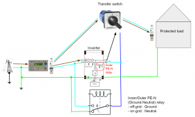
You have TN-C-S. There is a bond (a separation) from utility PEN to PE and N (here before the meter, many times after the meter ... no difference).
I used a manual transfer switch in the picture (that is allowed everywhere ... with ATS devices there are sometimes problems)
PE is never broken, never switched (star topology from main PE busbar).
Your inverter has an inner PE-N (double throw) relay ... works like the outer in the bottom.
Connects N_in to N_out in bypass mode. And connects PE to N_out in pure inverter mode.


Axpert_Victron_inner_relay.png
 
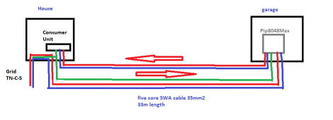
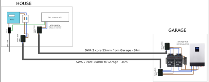
Another point to make is that I am doing 2 circuits in a SWA cable for a round trip.
Because all the solar stuff is in the garage, and there are around 33 meters to go there and back from the meter

1666021205373.png
 
Another point to make is that I am doing 2 circuits in a SWA cable for a round trip.
Because all the solar stuff is in the garage, and there are around 33 meters to go there and back from the meter

View attachment 116750

Even 16mm2 cable would be enough ... so 35mm2 is overkill :) The two pairs in separate cables would be safer.
Also if you have PV on garage, you need a ground rod there too (and one on your house side of course ).
They (busbars) need to be connected with az least 16mm2 copper.
PE-N bond on your house side only.
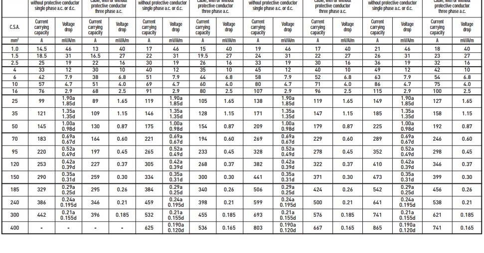
For the gauge it gets tricky :)

Buried single phase 16mm2 gives about 96amp capacity(which is great) I don't think I get anywhere near this - my consumption is 10KW day - 45 amp in total throughout the day, peak I may do around 32 in reality.
Buried 3 phase or 4 core is around 96amp for 25mm2 gauge, so 25mm2 for 2 phase should give me around 100amp(in theory) - for 2 circuits in the same system.

I did not find any earthing rod around my property, I think the ground is both piping and the bonding PEN.

Grounding the DC and the inverter how would it work?
- For the DC there should be ground to an earth rod from the surge arrestors?
- From the invertor, should it be grounded as well to an earth rod? If I would do 2 two grounds, they would be too close even if it is 4 meters any current discharged from the DC surge arrestor or other areas would flow back up the AC ground bar into the AC system(unless I really don't understand grounds)

Grounding is just a confusing topic even after all the videos and opinions are heated and wild.
 
For the gauge it gets tricky :)

Buried single phase 16mm2 gives about 96amp capacity(which is great) I don't think I get anywhere near this - my consumption is 10KW day - 45 amp in total throughout the day, peak I may do around 32 in reality.
Buried 3 phase or 4 core is around 96amp for 25mm2 gauge, so 25mm2 for 2 phase should give me around 100amp(in theory) - for 2 circuits in the same system.

Use this calculators. Stay below 3% (better below 2% loss)

I did not find any earthing rod around my property, I think the ground is both piping and the bonding PEN.

Here it needs to be better than 10 Ohm. I would put 4m (or 2x2m) grounding rod next to the house.
Also at least 2m next to the garage.


Grounding the DC and the inverter how would it work?
- For the DC there should be ground to an earth rod from the surge arrestors?
- From the invertor, should it be grounded as well to an earth rod? If I would do 2 two grounds, they would be too close even if it is 4 meters any current discharged from the DC surge arrestor or other areas would flow back up the AC ground bar into the AC system(unless I really don't understand grounds)

Grounding is just a confusing topic even after all the videos and opinions are heated and wild.

There is only one Earth one ground :)
So you need to connect everything to the same ground system.
Preferable is star configuration.

In this case 2 stars (2 busbars). One in the garage, one in the house. And they centers need to be connected to each other (at least 16mm2 copper cable).

The solar panel case needs to be connected to your garage ground busbar.
Your inverter needs to be connected here too (AC_in_PE and metal case both).
Your metal cabinet, your DC arrestors too

The house side use an AC surge arrestor on the main ;)
 
The solar panel case needs to be connected to your garage ground busbar.
Your inverter needs to be connected here too (AC_in_PE and metal case both).
Your metal cabinet, your DC arrestors too
By star you mean a non terminated ring in this case?
Like a single ground cable that has multiple rods - 1 by the garage, 2 by the house?
Any potential for ground loops in such a configuration?
 
By star topology I mean 1 busbar where all the PE lines connect.
There should be no other connection between PE cables.

This is one star for the the house side. The same for the garage side.

3-s2.0-B9780124077737000028-f02-03-9780124077737.jpg


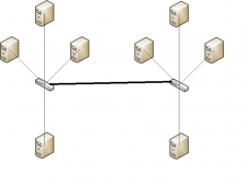
And the centrals (busbars) need to be connected like this:
Ground_stars.png
On both side 1-1 grounding rod connected to the central busbar.
 
Sorry, I was being an idiot, I was thought when you referred to the bus bars that you were referring to the earth connections

Here it needs to be better than 10 Ohm. I would put 4m (or 2x2m) grounding rod next to the house.
Also at least 2m next to the garage.
1-1 grounding means adding one rod(or two) per bus bar
 
I have been reading more about the grounding subject.
Grounding is generally to feed the power back to the source, the bonding aspect. It is also relevant for equipment protection which is why we use ground rods for discharges, etc
The context of switching, and also switching ground as well and bonding it after seems to be confusing.
I can't ground like you suggested unless the ATS also switches ground, otherwise I will be feeding fault current back to the main grid(in the case of faults). And from what I gather using RCBOs will do more for protection than adding more grounds here and there.

So is there a general problem about switching the ground as well? what am I missing here?
If the ATS switches all poles - ground, neutral and live(3pole):
- when connected to the mains the house is fully connected to the grid as standard.
- switching to generator/solar it is fully disconnected from the grid, including ground that then would be bonded and also have a ground rod.

Do you see any problems arising from this?
 
Last edited:
I have been reading more about the grounding subject.
Grounding is generally to feed the power back to the source, the bonding aspect. It is also relevant for equipment protection which is why we use ground rods for discharges, etc
The context of switching, and also switching ground as well and bonding it after seems to be confusing.
I can't ground like you suggested unless the ATS also switches ground,

It is not allowed to break or switch PE in any case.

otherwise I will be feeding fault current back to the main grid(in the case of faults). And from what I gather using RCBOs will do more for protection than adding more grounds here and there.

You have a grounding rod so you will not feed back fault current.
RCBO's and RCD's only work because you have a good grounding. If grounding is bad, big resistance ... then they work less.

So is there a general problem about switching the ground as well? what am I missing here?
If the ATS switches all poles - ground, neutral and live(3pole):
- when connected to the mains the house is fully connected to the grid as standard.
- switching to generator/solar it is fully disconnected from the grid, including ground that then would be bonded and also have a ground rod.

Do you see any problems arising from this?
ATS only switches Line and Neutral. Never the ground.
 
It is not allowed to break or switch PE in any case.


You have a grounding rod so you will not feed back fault current.
RCBO's and RCD's only work because you have a good grounding. If grounding is bad, big resistance ... then they work less.


ATS only switches Line and Neutral. Never the ground.
So I am stumped at ground design.
In the UK I have TNC-S, the ground goes from the consumer unit to bond with N at the source(PEN).
Now if the Hybrid setup connects to the same ground, if there is a fault, it injects it into the grid, so it cannot be said to be fully offgrid.
How do I ground this?
1675017785936.png
 
Back
Top