Main Panel LNG->Growatt LNG-> Reliance TS( installed by electrician with inspection). When I power TS by GW battery mode I can run circuits in the house from TS. When I connect AC input the AC input breaker pops in the main panel immediately.When you say 'It works' or 'it doesn't work' what do you mean? Do you mean the loads do/don't work or do you mean there is a problem with the bonding? Could you provide a diagram of what you have hooked up?


You are using an out of date browser. It may not display this or other websites correctly.
You should upgrade or use an alternative browser.
You should upgrade or use an alternative browser.
Growatt 3000 SPF Floating Neutral (Solved for Now)
- Thread starter ChrisG
- Start date
FilterGuy
Solar Engineering Consultant - EG4 and Consumers
That is odd.Main Panel LNG->Growatt LNG-> Reliance TS( installed by electrician with inspection). When I power TS by GW battery mode I can run circuits in the house from TS. When I connect AC input the AC input breaker pops in the main panel immediately.
On the reliance, if you put all of the breakers to the 'off' position, does the AC-in breaker still pop?
FilterGuy
Solar Engineering Consultant - EG4 and Consumers
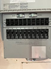
The reliance is typically installed with the hot line looping through the main breaker and the Neutral and Ground coming from the main breaker.
Is this what you have?
EDIT: Made the circuit diagram slightly more readable... But it is still the same circuit.

Does the breaker that pops have ground fault protection?
Is this what you have?
EDIT: Made the circuit diagram slightly more readable... But it is still the same circuit.
Does the breaker that pops have ground fault protection?
Last edited:
FilterGuy
Solar Engineering Consultant - EG4 and Consumers
Notice that in the drawing in my previous post, the input and output neutrals are connected together. Growatt said to do this for the older versions of the inverter, but it is not clear if this is supported on the newer versions.
My guess is that the breaker is poping for one of a few reasons.
1) The wiring is wrong. If the Line and neutral on either the input or output got swapped, it would pop the breaker in pass-through but not in inverter mode.
2) The breaker has GFCI protection and the Neutral bonding got duplicated inside the inverter (This would mean you have the new version of the inverter).
3) The inverter is bad.
I have the older version based on what you said above so I need to jump neutral. It is the reliance TS where the hots get swapped like you have above. The circuit powering GW has GFCI breaker in the panel. I can swap to normal for testing. It pops as soon as the inverter clicks for bypass mode.
Need to test:
1. With neutral jumper again
2. With all TS switches in off position to start
3. With normal breaker for circuit powering AC input on GW.
Need to test:
1. With neutral jumper again
2. With all TS switches in off position to start
3. With normal breaker for circuit powering AC input on GW.
FilterGuy
Solar Engineering Consultant - EG4 and Consumers
It will be interesting to see if going to a 'normal' breaker makes a difference.I have the older version based on what you said above so I need to jump neutral. It is the reliance TS where the hots get swapped like you have above. The circuit powering GW has GFCI breaker in the panel. I can swap to normal for testing. It pops as soon as the inverter clicks for bypass mode.
Need to test:
1. With neutral jumper again
2. With all TS switches in off position to start
3. With normal breaker for circuit powering AC input on GW.
Have not tested yet, plan is later today. I did read a thread on here with a LV6048 where a certain type of Transfer Switch had to be used that also switch neutral. Any thoughts on that?It will be interesting to see if going to a 'normal' breaker makes a difference.
FilterGuy
Solar Engineering Consultant - EG4 and Consumers
With a transfer switch that does not switch neutral, the system ends up with neutral-in tied to neutral out on the inverter. There are a few big questions that need to be addressed in this case.Have not tested yet, plan is later today. I did read a thread on here with a LV6048 where a certain type of Transfer Switch had to be used that also switch neutral. Any thoughts on that?
1) Does it work? As best as I can tell, it seems to work with many (most?) inverters.
2) How is N-G bonding handled? For the older version of the GW 3K, there is no internal bonding so this works well. For the newer version of the GW 3K or any other inverter that has dynamic bonding, the bonding must be disabled.
3) Is it supported? This is far less clear. For the older versions of the Growatt 3K, they said it is supported. I have not heard a definitive statement from Growatt, MPP or EG4 on any of the units that do internal bonding.
It is very frustrating that the manufacturer didn't provides details on what should be done on the options you choose to install. My SPF 3K LVM-ES model has N-G continuity on AC output and I didn't have "open neutral " on the AC output receptacles which I am happy to see.With a transfer switch that does not switch neutral, the system ends up with neutral-in tied to neutral out on the inverter. There are a few big questions that need to be addressed in this case.
1) Does it work? As best as I can tell, it seems to work with many (most?) inverters.
2) How is N-G bonding handled? For the older version of the GW 3K, there is no internal bonding so this works well. For the newer version of the GW 3K or any other inverter that has dynamic bonding, the bonding must be disabled.
3) Is it supported? This is far less clear. For the older versions of the Growatt 3K, they said it is supported. I have not heard a definitive statement from Growatt, MPP or EG4 on any of the units that do internal bonding.
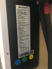
Just in case you communicate with Growatt and you also wanted to update the model on your list that this is my Model Number.

FilterGuy
Solar Engineering Consultant - EG4 and Consumers
It is beyond frustrating..... It is nearly criminal negligence that they do not provide the info to safely use the product!!!It is very frustrating that the manufacturer didn't provides details on what should be done on the options you choose to install.
You have confirmed something that I was beginning to worry about..... What Growatt told me about the model number is not correct.My SPF 3K LVM-ES model has N-G continuity on AC output and I didn't have "open neutral " on the AC output receptacles which I am happy to see.
Just in case you communicate with Growatt and you also wanted to update the model on your list that this is my Model Number.

Just in case you talk to them, you have my Model number.It is beyond frustrating..... It is nearly criminal negligence that they do not provide the info to safely use the product!!!
You have confirmed something that I was beginning to worry about..... What Growatt told me about the model number is not correct.
So this video describes exactly what I want to do. In my test case I want the Gw3000 in UTIL mode always powering the circuits in the Transfer Switch and fail over to battery when needed. TS will always be in GEN mode (power always comes from GW either UTIL or Battery). If there is an issue or maintenance I can put the circuits back to LINE mode which feeds the circuits directly from grid.
FilterGuy
Solar Engineering Consultant - EG4 and Consumers
@ChrisG Based on that video I am 99% sure the inverter is not doing dynamic bonding. That means you have an older version of the inverter. Growatt told me that for the older versions like you have the input and output neutrals should be connected (Common neutral). With a common neutral, the Reliance breaker (no neutral switching) should be fine.Here is a video of my GW3000. Specifically testing G/N bonds as well as G/G and N/N continuity on battery and on UTIL
Thank you very much for the review @FilterGuy. You have been so helpful through this process. So in theory, this should make it safe to use with both UTIL and Batt/Sol as long as I jump the neutrals. Goal for this test is to have two circuits always run in bypass mode that has our fridge and freezers on it. When the power goes out I have 10 kWh of LifePo4 to support it. Reliability is a completely different question that time will tell.@ChrisG Based on that video I am 99% sure the inverter is not doing dynamic bonding. That means you have an older version of the inverter. Growatt told me that for the older versions like you have the input and output neutrals should be connected (Common neutral). With a common neutral, the Reliance breaker (no neutral switching) should be fine.
Ok, reporting back with neutrals jumped and using Reliance Transfer switch. Some great news and some ok news:
1. The great: Having Growatt AC Input come from a non GFCI/AFCI breaker worked. I was able to power my house circuits on my transfer switch using both ac bypass and battery. Even tried microwave on both AC Bypass and Battery. Worked great. Even simulated a power outage by tripping the input GW AC breaker and wife said she noticed a slight flicker in lights, that was it and running on battery
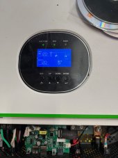
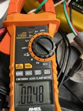
2. The Ok news: As I brought on more circuits and load from the TS switch, the amps on the ground increased BUT there was no voltage between neutral and ground on both AC INPUT and OUPUT. Still trying to explain that. On input and output it was 0V N-G, 120v G-L1, 120v L1-N. At 1300W load, I had .48A on ground; near full capacity at 2700 watts, I had 1.1A on the ground. Any thoughts?
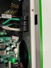
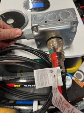
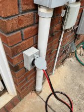
Excuse the mess in my pictures, rolling testing bench.
1. The great: Having Growatt AC Input come from a non GFCI/AFCI breaker worked. I was able to power my house circuits on my transfer switch using both ac bypass and battery. Even tried microwave on both AC Bypass and Battery. Worked great. Even simulated a power outage by tripping the input GW AC breaker and wife said she noticed a slight flicker in lights, that was it and running on battery
2. The Ok news: As I brought on more circuits and load from the TS switch, the amps on the ground increased BUT there was no voltage between neutral and ground on both AC INPUT and OUPUT. Still trying to explain that. On input and output it was 0V N-G, 120v G-L1, 120v L1-N. At 1300W load, I had .48A on ground; near full capacity at 2700 watts, I had 1.1A on the ground. Any thoughts?
Excuse the mess in my pictures, rolling testing bench
.Attachments
FilterGuy
Solar Engineering Consultant - EG4 and Consumers
That explains why the GFI was tripping. GFCI in the United States is generally designed to trip at something less than 0.01A on the ground.I had .48A on ground; near full capacity at 2700 watts, I had 1.1A on the ground. Any thoughts?
Now the big question becomes: Where is that current coming from? It seems too low for it to be from a 2nd NG bond. (With 2 NG bonds on a 120V circuit, the current on the ground would be closer to 1/2 the total current.)
My first guess is leakage from the inverter. An interesting experiment would be to disconnect the outputs from the inverter and see if there is still current on the ground.
Ok. Another test complete:That explains why the GFI was tripping. GFCI in the United States is generally designed to trip at something less than 0.01A on the ground.
Now the big question becomes: Where is that current coming from? It seems too low for it to be from a 2nd NG bond. (With 2 NG bonds on a 120V circuit, the current on the ground would be closer to 1/2 the total current.)
My first guess is leakage from the inverter. An interesting experiment would be to disconnect the outputs from the inverter and see if there is still current on the ground.
Still 0 V on G/N on AC in or Out in ALL tests:
UTIL Mode
1. AC Input No Loads; simply connected to Transfer Switch = 0amps on G
2. Flip circuit on TS from Grid to inverter with loads off = 0amps on G
3. AC Input with same test as yesterday = 1500w is .43a, 2790w is 1.1a.
SBU Mode- AC input still connected
1. 0V on G/N on AC In and AC Out, .02a on G under 2790w load.
yadaninetyone
New Member
- Joined
- Jun 16, 2022
- Messages
- 6
I'm posting my model number as FYI. My growatt does NOT have internal NG bonding. Does NOT bond neutral in to out. Sig solar is NOT helpful and Growatt didn't respond. Can't say I blame sig solar as they were given the same info as we have. Thanks again to filterguy for all your help!

Attachments
FilterGuy
Solar Engineering Consultant - EG4 and Consumers
The good news is that there is an easy test to determine if the GW inverter has the internal dynamic bonding: With the inverter disconnected from everything, check for continuity between Neutral out and Ground. If there is continuity, there is internal dynamic bonding.
Similar threads
- Replies
- 6
- Views
- 264
- Replies
- 13
- Views
- 720
- Replies
- 1
- Views
- 197
- Replies
- 4
- Views
- 777