diy solar

diy solar

Heater element matched to solar panel output = diode string

MattiFin

Solar Addict
Joined
Dec 31, 2020
Messages
713
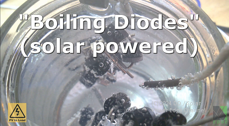
Was thinking of solar panel matching to resistive heater when it occurred to me that diode string as a heater would be almost perfect match to solar panel output characteristics (at least compared to resistive heater)

Comes with some obvious limitations like limited temperature range and need to connect gazillion diodes in series but might actually prove usable in some small scale project? 🫣
 
I think it's easier to match a set of panels to the resistive heating element. Then, adding a capacitor and PWM the output, and you've got a pretty effective system.
 
Resistive load in partial sun would get less current, operate at lower voltage further from maximum power point.

Diodes only decrease in voltage a little bit when current decreases a lot, closer match to PV curve. Doesn't adjust for shaded panel in a string, however.

The fancier alternative is the PWM circuit you mention. For a resistive load, it can operate as MPPT without inductors needed.
 
Diodes would work, but there are two disadvantages.
Max temperature of the silicon junction, about 160 Celsius, above which your diode fails short circuit.
Cost of a very large number of high power diodes.

A much better solution would be to use a simple resistive heating element, and a switching voltage regulator, to adjust the loading on the solar panels to keep the solar panel voltage very close to the maximum power voltage.
 
some more info might be nice...


It's a way to hook up solar panels to water heating elements. I'm building two of these to help offset electricity use at my in-laws, with an 8kW array hooked up to the 3-phase heating elements in the 2500L tank (used for domestic hot water and the floor heating). @Steve T - IoW UK is the person behind the LoadMaster.
 

It's a way to hook up solar panels to water heating elements. I'm building two of these to help offset electricity use at my in-laws, with an 8kW array hooked up to the 3-phase heating elements in the 2500L tank (used for domestic hot water and the floor heating). @Steve T - IoW UK is the person behind the LoadMaster.
Thanks.. whats your real name again? sorry I am a retard but I like to say thanks to people in real time...
 
All this seems excessively complicated given the application...

Why not just buy more cheap panels from SanTan than you know you will actually need, hook 'em up to more resistive elements than the minimum necessary to meet your requirements, be aware that there will be a mismatch, and get on with it?

I don't get it...in my experience simple is better. Less points of failure, less cost.
 
Because the amount of space for panels is limited, because matching resistance of a heating element with panels means a certain amount of panels (and panel combination) is needed, because even if you match the panels with the resistance it's only optimal in one case and will produce far less than the panels are capable of when it's not exactly noon, because the amount of heating elements in a tank is limited and adding another one is expensive and difficult or impossible, etc.
 
All this seems excessively complicated given the application...

Why not just buy more cheap panels from SanTan than you know you will actually need, hook 'em up to more resistive elements than the minimum necessary to meet your requirements, be aware that there will be a mismatch, and get on with it?

I don't get it...in my experience simple is better. Less points of failure, less cost.
Mismatch gets pretty awful when conditions get worse. If light levels are 10% of the rated STC conditions the direct resistive connection needs 10 times more panels than MPPT matched panel. 1kW vs 10kW of panels might sting your wallet even with the current prices.

I guess you could also match the resistive load to bad weather conditions and take the hit on good weather performance... could make sense in some cases if you have no use for the excess solar energy during nice weather.
 
Okay, points taken. All that makes sense for northerly locations with limited roof space.

I am not constrained by either, so was coming from that point of view. I am also 20 min. drive from SanTan, so the ability to throw cheap power around tends to shape how I do things.

I need to get out more ;-) There's a whole world out there...
 
I guess you could also match the resistive load to bad weather conditions and take the hit on good weather performance... could make sense in some cases if you have no use for the excess solar energy during nice weather.

With two elements in a water heater, you've got at least three different I/V operating points available by switching.

Extra PV panels in parallel, and of different orientations, would be a good way to maintain one operating point (plus about 10% ~ 15% voltage increase Voc vs. Vmp).
 
With two elements in a water heater, you've got at least three different I/V operating points available by switching.

Extra PV panels in parallel, and of different orientations, would be a good way to maintain one operating point (plus about 10% ~ 15% voltage increase Voc vs. Vmp).
Good thinking...But how do you switch DC without killing the switchgear due to arcing?
 

It's a way to hook up solar panels to water heating elements. I'm building two of these to help offset electricity use at my in-laws, with an 8kW array hooked up to the 3-phase heating elements in the 2500L tank (used for domestic hot water and the floor heating). @Steve T - IoW UK is the person behind the LoadMaster.

https://www.bel-shop.eu/controller-for-boiler-suplying-from-solar-panels-mr4316ac-ng-to-switchboard/

This is a commercially available alternative to Loadmaster allowing use of standard immersions inc mechanical thermostats. Not seemingly as elegant but available off the shelf or as a kit. It allows connection of AC resistive elements, to which it feeds 122Hz PWM, plus a DC connection, I assume to existing MPPT. It periodically looks for the presence/absence of each of the loads & will prioritise whichever one you choose.

I would much rather use Loadmaster, not least because all the documentation is in English, but I just can't get motivated to get everything lined up to build, test deploy. I would enjoy it but I just can't squeeze as many productive hours into a day as ai used to!
 
It's a way to hook up solar panels to water heating elements. I'm building two of these to help offset electricity use at my in-laws, with an 8kW array hooked up to the 3-phase heating elements in the 2500L tank (used for domestic hot water and the floor heating). @Steve T - IoW UK is the person behind the LoadMaster.
If you have 8kW array, rather just a panel or two, would it not be more useful to connect them to an inverter to power the house and then use an AC based immersion diverter? Surely an 8kW array would generate more hot water than anyone could usefully use - unless you are talking of swimming pools or hot tubs?
 
If you have 8kW array, rather just a panel or two, would it not be more useful to connect them to an inverter to power the house and then use an AC based immersion diverter? Surely an 8kW array would generate more hot water than anyone could usefully use - unless you are talking of swimming pools or hot tubs?
Increasing the inverter size to cope with extra heating (which is probably the biggest load) has several disadvantages
1. You might not be allowed to connect the larger inverter to the grid
2. Having a larger inverter used with a smaller load means you're operating in a very inefficient region of operation
3. You can be looking at over 100W of parasitic load on the larger inverters, just to operate maybe a 3W router and a 20W fridge
4. it costs more
 
If you have 8kW array, rather just a panel or two, would it not be more useful to connect them to an inverter to power the house and then use an AC based immersion diverter? Surely an 8kW array would generate more hot water than anyone could usefully use - unless you are talking of swimming pools or hot tubs?

Hot water tanks n this case are several thousand liters. They're buffers hooked up to e.g. wood burners, and they have extra electric heating elements. These buffers are both for domestic hot water as well as the floor heating.

When adding them directly to the house, you need a grid tie inverter etc. This is just a cable running from the panels to the heating element without the cost of the inverter and need to comply with the installation guidelines of a grid tie system.
 
Increasing the inverter size to cope with extra heating (which is probably the biggest load) has several disadvantages
1. You might not be allowed to connect the larger inverter to the grid
2. Having a larger inverter used with a smaller load means you're operating in a very inefficient region of operation
3. You can be looking at over 100W of parasitic load on the larger inverters, just to operate maybe a 3W router and a 20W fridge
4. it costs more
(y) That makes sense... In my case, however, I have the inverter to power the house anyway, so it's just excess that I use to heat water using an AC-based immersion diverter.
 
Good thinking...But how do you switch DC without killing the switchgear due to arcing?

That can be a problem.

If you have 2 elements in series and short one out or open switch to include it, current flows through resistor so voltage won't jump too high.

I think some SSR are MOSFET, should work for DC. (SCR don't open until a zero crossing.)
Thermostat and over-temperature switch ought to work for pilot duty, controlling a suitably rated contactor. But safety switch I do want something failsafe. Be sure to have temperature/pressure relief valve.


Contacts and transistors could be protected with RC snubber. Most important switching inductive loads.

There is an MPPT design for heating elements. It doesn't need inductors, just has a capacitor on PV side, uses PWM into resistor to vary power.
 
There is an MPPT design for heating elements. It doesn't need inductors, just has a capacitor on PV side, uses PWM into resistor to vary power.
That is the simplest and most efficient way to do it.

Connect a relatively large capacitor across the solar voltage source (thousands to tens of thousands of uF recommended).
That will be charged continuously by current from the solar panels.
Allow the combined voltage to rise above the rated maximum power panel voltage (MPP shown on the solar panel ratings plate).
When the upper threshold voltage is reached, connect both the combined solar source and capacitor to the heating element by switching on a mosfet.

The heating element will then discharge the capacitor, pulling the solar voltage down.
Allow the voltage to fall to a lower voltage below the rated peak power voltage.
Turn the mosfet off, allowing the voltage to again rise.

The voltage across both solar panels and capacitor ramps up and down between two set voltage thresholds.
The system cycles or oscillates at a relatively low frequency. In effect very slow motion pulse width modulation.
These voltage thresholds are set to be either side of the maximum rated power voltage, thus always maintaining the solar voltage fairly close to the maximum peak power point from twilight to full sun.

The heating element resistance should be kept "reasonable" but is not absolutely critical.
It will discharge the capacitor pretty much regardless of the actual resistance.
Power transfer efficiency will remain high over a very wide range of solar, and a reasonable range heating element resistance.

In gloomy conditions, the cycling rate will become very slow, but it will still pulse power into the heating element without overloading the solar panels.

Some kind of transient voltage suppression across the mosfet will be required, quite a few different approaches to that.
An avalanche rated mosfet will work very well (at a low enough repetition rate) so will a fast diode back to the solar capacitor, or even a simple snubber.
If the controller is located fairly close to the heating element there should not be much series inductance there to cause a problem.

If the capacitor is made large, the system will cycle slow enough (in the order of seconds) that any switching losses will be negligible.
While the system is cycling on and off, the capacitor charging current from solar remains constant.
Quite a few of these have been successfully built, and they work amazingly well.

*hint* A standard garden variety 555 timer chip contains two voltage comparators connected to the set and reset inputs of a flip flop.
This can be run in normal astable mode, using the high voltage solar capacitor, and two separate adjustable voltage dividers.
Output of the 555 will need to be inverted to drive the mosfet gate.
 
Last edited:
Typical commercial MPPT charge controllers recharging a battery, will seek and hold the peak power voltage during bulk recharging of the battery.

Once the controller goes into absorb or float mode, loading on the solar panels is throttled back, and panel voltage is allowed to rise up towards full open circuit voltage with a decreasing battery charging load.

Now one of these capacitor ramping hot water heaters COULD be set up to only operate at voltages a bit higher than the main MPPT battery charging controller ever uses running flat out bulk charging.
So hot water heating power is off, until the main MPPT controller starts shedding load and the solar voltage begins to rise above the normal MPPT controller voltage operating range.
It will require a bit of very careful tweaking of voltage thresholds, but should be workable.

Its going to be less efficient than tuning the hot water ramping voltage controller range for full maximum power transfer, but with a bit of careful adjustment it might be able to use any excess solar for water heating once the battery is full ?

I have not actually tried this myself yet with a commercial software MPPT controller, so its just speculative.
Although it definitely works very well with my own constant solar voltage hardware MPPT controller.
 

diy solar

diy solar
Back
Top